A multi-level worm wheel blade adjustment mechanism

A worm gear and adjusting mechanism technology, which is applied to wind turbines, control of wind turbines, engines, etc., can solve problems such as poor synchronization, unsatisfactory power generation cost, and unsatisfactory blade angle control, achieve a large transmission ratio, and improve wind energy utilization. Efficiency and convenient routine maintenance

CN104989593BInactive Publication Date: 2017-11-17张效新 +1
8 Cites 0 Cited by

Patent Information

Authority / Receiving Office
CN · China
Patent Type
Patents(China)
Current Assignee / Owner
Publication Date
2017-11-17
Estimated Expiration
Not applicable · inactive patent

Smart Images

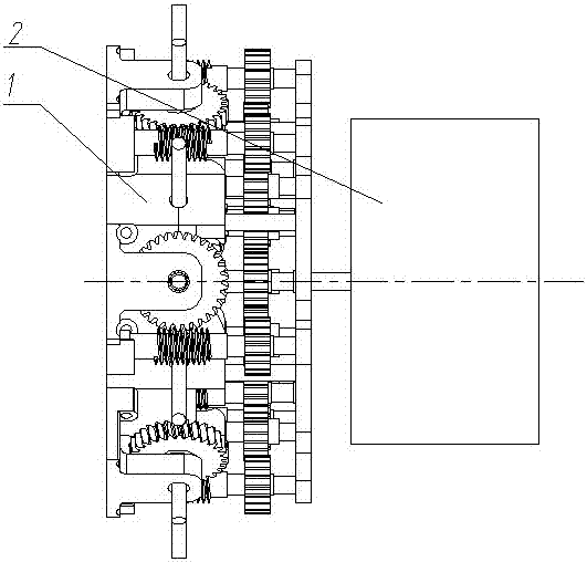
  • Figure 1
    Figure 1
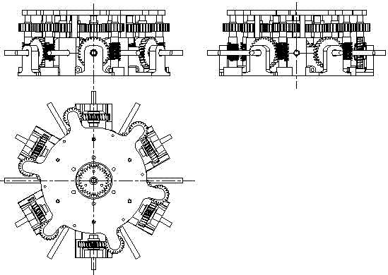
  • Figure 2
    Figure 2
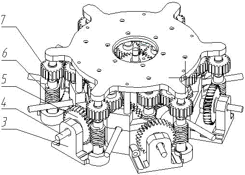
  • Figure 3
    Figure 3
Patent Text Reader

Abstract

The invention relates to the technical field of wind power generation equipment, in particular to a multilayer worm-and-gear wind turbine blade adjusting mechanism to solve the problems that an adjusting mechanism in the conventional toothed wheel technology requires a large torque on the adjusting mechanism, the adjusting mechanism is poor in reliability, and a blade angle is difficult to control. The multilayer worm-and-gear wind turbine blade adjusting mechanism comprises worm toothed wheel seats, outer layer supporting frames, engine room cylinder walls, a driving motor fixing disk, a toothed wheel mechanism and a worm-and-gear mechanism; the engine room cylinder walls are connected with the driving motor fixing disk; the worm toothed wheel seats are mounted on the engine room cylinder walls; the outer layer supporting frames are uniformly mounted on the outer sides of the worm toothed wheel seats; four transmission toothed wheels are assembled surrounding a main driving toothed wheel from inside to outside and are engaged sequentially; inner layer gears are mounted at the end parts of blade shafts on the inner sides of the worm toothed wheels seats; and outer layer gears are mounted at the end parts of blade shafts on the inner sides of the outer layer supporting frames. Through changing the structure of the adjusting mechanism and the transmission mode, the transmission stability and the accuracy are improved.
Need to check novelty before this filing date? Find Prior Art

Description

technical field

[0001] The invention relates to the technical field of wind power generation equipment, in particular to a multi-level worm wheel and worm type wind wheel blade adjustment mechanism. Background technique

[0002] The wind turbine blade adjustment mechanism is connected with the power unit to drive the main transmission gear to rotate, and the windward angle of the blade is adjusted through the transmission of the transmission mechanism.

[0003] At present, some wind turbine blades are installed at a fixed angle, and some are independently adjusted for the angle of each blade. The independent adjustment of blade angle is poor in synchronization.

[0004] In addition, the gear structure of a single-frame impeller disclosed in the invention patent application number 201410561011.7 and the utility model patent ZL201420608931.5 is also not ideal in terms of blade angle control. As a result, the overall operation and unit power generation cost are still unsatisf...

Examples

Embodiment

[0018] Depend on Figure 1 to Figure 4 It can be seen that the technical solution of the present invention includes a worm gear seat 8, an outer support frame 3, a blade shaft 4, a cylinder wall 9, a drive motor fixed plate 12, an outer worm wheel 5, an outer worm 6, an inner worm 10, The inner worm gear 13, the main transmission gear 11, and the gear 7; the power unit 2 is placed on the side of the drive motor fixed plate of the adjustment mechanism 1 as a whole;

[0019] The overall adjustment mechanism 1 is a worm gear adjustment mechanism; the power unit 2 for adjusting and controlling the blade angle in this embodiment adopts an electric motor; The transmission gear shaft is located in the center of the inner side of the worm gear seat 8, and the cylindrical wall 9 of the engine room is connected to the fixed plate 12 of the driving motor. There is a hole for assembling the blade shaft 4, the outer support frame 3 is evenly installed on the outside of the worm gear seat ...