pressure reducing valve

A pressure reducing valve and main valve technology, applied in the field of pressure reducing valves, can solve the problem that the pressure reducing valve is easy to vibrate, and achieve the effect of avoiding vibration

Active Publication Date: 2018-09-18
ROBERT BOSCH GMBH
View PDF10 Cites 0 Cited by
  • Summary
  • Abstract
  • Description
  • Claims
  • Application Information

AI Technical Summary

Problems solved by technology

The disadvantage of this solution is that the entire pressure reducing valve is prone to vibrations

Method used


Image

  • pressure reducing valve
  • pressure reducing valve

Examples


Embodiment Construction

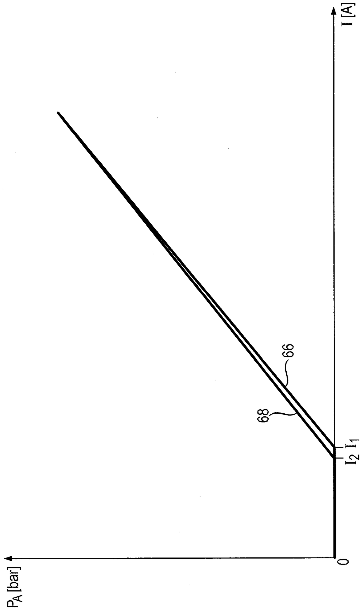
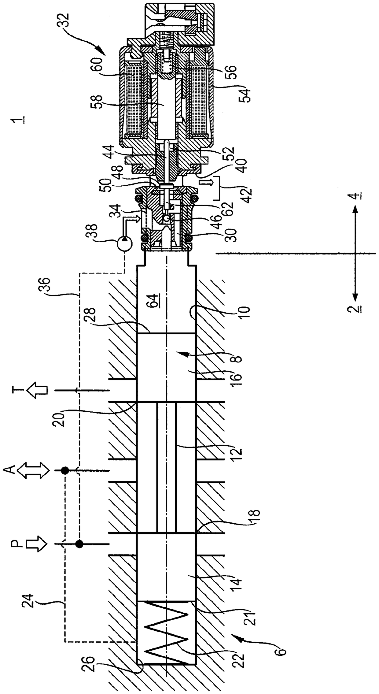
[0073] according to figure 1 A pressure relief valve 1 is shown. The pressure reducing valve is a pre-adjusted 3-way-pressure reducing valve. Such pressure reducing valves are used, for example, in load control transmissions of passenger cars, trucks, buses, construction machines or tractors. In addition, it is suitable for many common hydraulic applications, such as for actuating large directional valves, power brakes, fan drives, hydraulic pumps or hydraulic motors. The pressure relief valve is less susceptible to vibration and has less loss of control oil. It can be used for higher pressures and higher pressure medium volume flows.

[0074] The pressure reducing valve 1 has a main stage 2 and a prestage 4 . The main stage 2 has a main valve 6 . The pressure medium connection between the control oil connection P and the outlet connection A and between the outlet connection A and the tank connection T can be controlled by a control element in the form of a control piston...


PUM


Abstract

The invention relates to a pressure reducing valve with a main valve and a preset valve. The pressure relief valve controls the opening cross-section between the control oil connection and the outlet connection and the opening cross-section between the outlet connection and the tank connection as a function of the preset pressure set by the preset valve. The presetting valve keeps a set presetting pressure constant during pressure regulating operation. The presetting valve has at least one presetting element with which a first opening cross section between a control oil connection and a presetting connection fluidically connected to the main valve can be controlled. Furthermore, with the at least one presetting element, a second opening cross section between the presetting connection and the discharge connection can be controlled. During the pressure regulation operation for regulating the presetting pressure, the two opening cross sections are open.

Description

technical field [0001] The invention relates to a pressure reducing valve according to the preamble of claim 1 , in particular a preadjusted pressure reducing valve. Background technique [0002] A pressure reducing valve maintains a constant output pressure (secondary pressure) as the input pressure (primary pressure) varies. [0003] Such a pressure relief valve is disclosed in the laid-open document DE 35 37 336 A1. Such a pressure reducing valve has a distribution valve as main stage and a regulating valve as upstream stage. The secondary pressure is regulated within specified pressure limits with the pressure regulating valve. If the secondary pressure exceeds the pressure limit, the spool of the distribution valve is actuated in such a way that the control oil connection is directly connected to the output connection and the connection is no longer made via the control valve. The disadvantage of this solution is that the entire pressure reducing valve is prone to vi...

Claims


Application Information

Patent Timeline
Patent Type & Authority Patents(China)
IPC IPC(8): F15B13/043F16K31/06
CPCG05D16/2093G05D16/2097G05D16/2024Y10T137/7762Y10T137/87209Y10T137/86614F16K17/10
Inventor J.帕斯图施卡L.蔡泽
Owner ROBERT BOSCH GMBH
Why Eureka
Try Eureka