

Pressure reducing valve
Patent Information
- Authority / Receiving Office
- CN · China
- Current Assignee / Owner
- ROBERT BOSCH GMBH
- Publication Date
- 2015-09-23
Smart Images
Figure 1 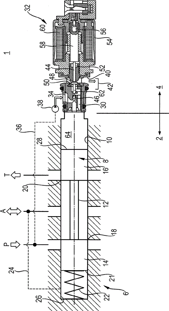
Figure 2
Abstract
Description
technical field
[0001] The invention relates to a pressure reducing valve according to the preamble of claim 1 , in particular a preadjusted pressure reducing valve. Background technique
[0002] A pressure reducing valve maintains a constant output pressure (secondary pressure) as the input pressure (primary pressure) varies.
[0003] Such a pressure relief valve is disclosed in the laid-open document DE 35 37 336 A1. Such a pressure reducing valve has a distribution valve as main stage and a regulating valve as upstream stage. The secondary pressure is regulated within specified pressure limits with the pressure regulating valve. If the secondary pressure exceeds the pressure limit, the spool of the distribution valve is actuated in such a way that the control oil connection is directly connected to the output connection and the connection is no longer made via the regulating valve. The disadvantage of this solution is that the entire pressure reducing valve is prone to...