Fuel cell vehicle

a fuel cell and vehicle technology, applied in the direction of cell components, electrochemical generators, cell component details, etc., can solve the problems of difficult mounting position of the mount member, inability to fully secure the support rigidity relative to the housing case of the fuel cell, and quiet sound

Inactive Publication Date: 2006-06-01
HONDA MOTOR CO LTD
View PDF4 Cites 57 Cited by
  • Summary
  • Abstract
  • Description
  • Claims
  • Application Information

AI Technical Summary

Benefits of technology

[0030] According to the fuel cell vehicle, a common hydrogen sensor can conduct measurement of the hydrogen concentration in the vicinity of the fuel cell stacks and the hydrogen system accessory where the hydrogen concentration would seem to be higher compared to other accessory equipment. Accordingly, measurement can be quickly conducted in a short period of time by the hydrogen sensor, and that the prescribed protective operations can be adopted.

Problems solved by technology

Accordingly, when the feed pipes of the reaction gas and the coolant vibrate, this is transmitted to the fuel cells, which is undesirable and which tends to ruin quiet in the vehicle compartment.
Conventional fuel cell vehicles have the merit of being able to elastically support the fuel cells relative to the housing case via the mount members, but there is the problem that it is not possible to fully secure support rigidity relative to the housing case of the fuel cells.
Moreover, there is the problem that it is difficult to set the placement positions of the mount members.
In this regard, when the measurement accuracy of the hydrogen sensor is low, there is the problem that this engenders the trouble of having to conduct ventilation more than is necessary.
When a plurality of hydrogen sensors are provided in order to raise measurement accuracy, there is the problem that it leads to higher cost.

Method used


Image

  • Fuel cell vehicle
  • Fuel cell vehicle
  • Fuel cell vehicle

Examples


first embodiment

[0048] Next, the invention is explained with reference to drawings.

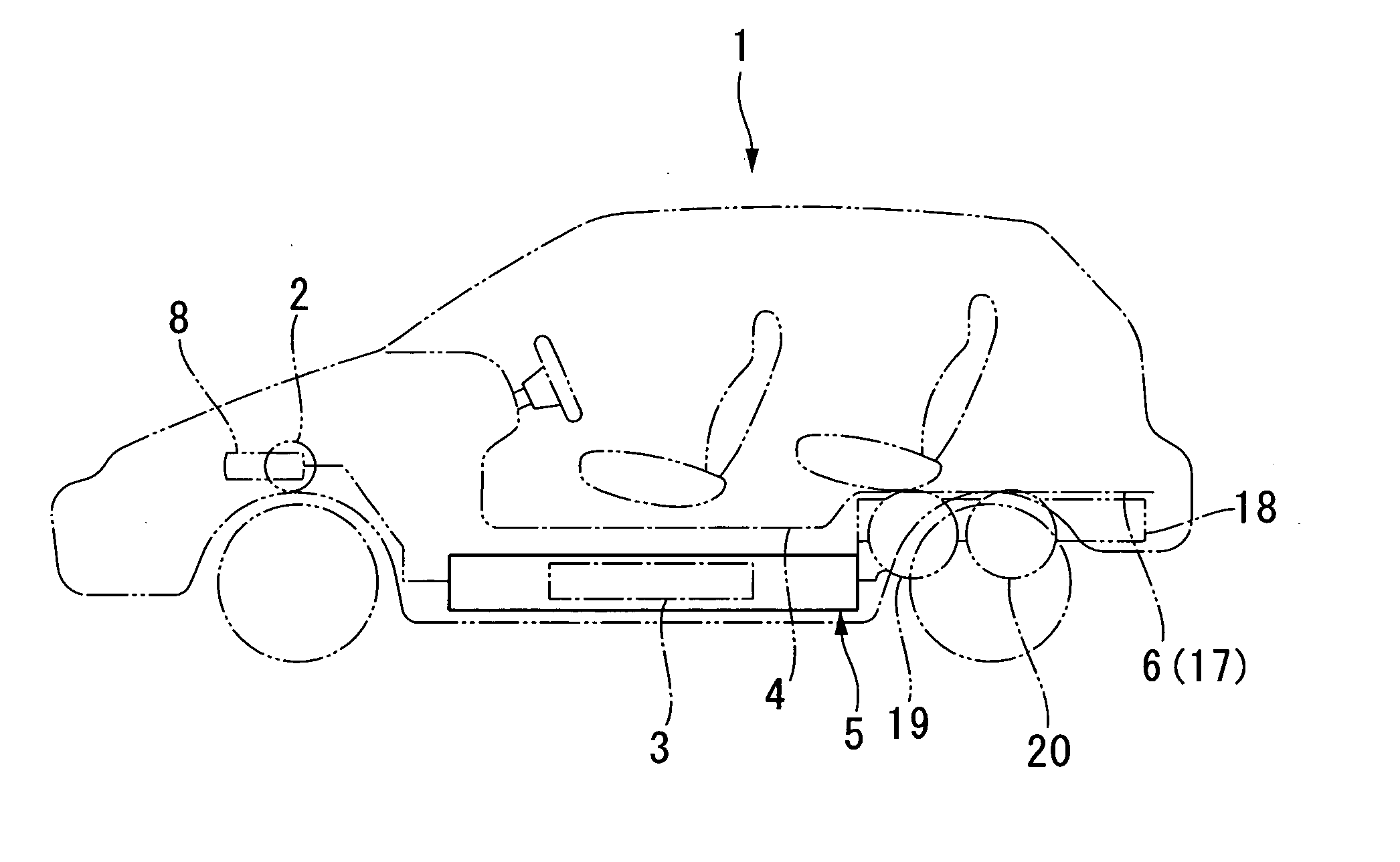
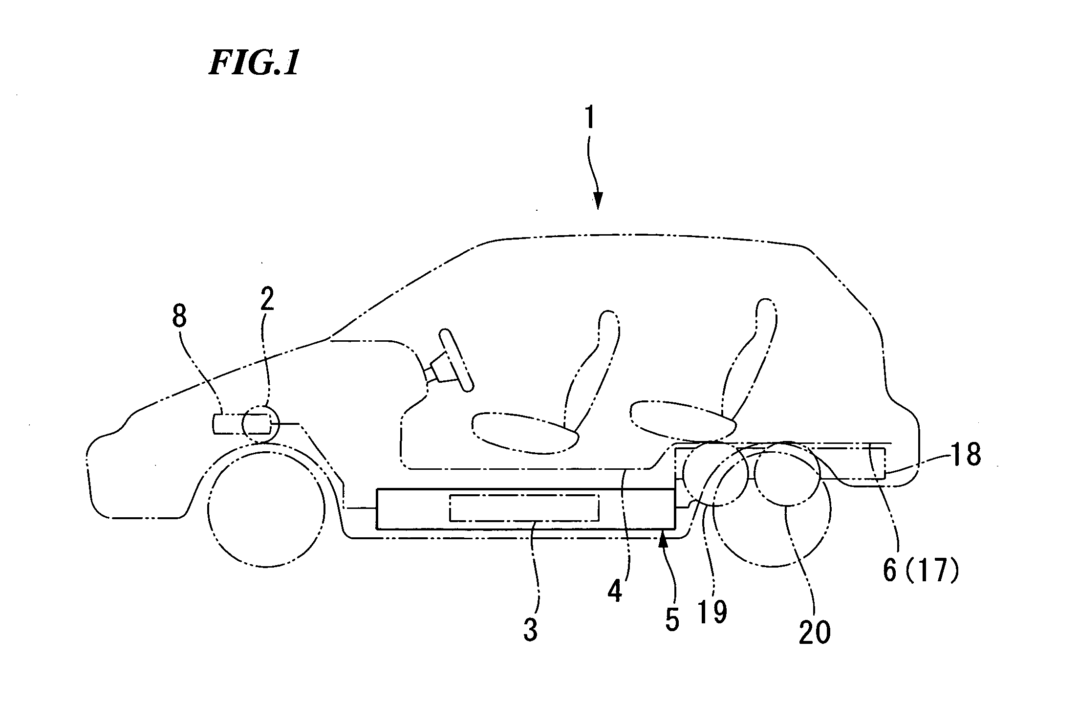
[0049] As shown in FIG. 1, the fuel cell vehicle 1 mounts fuel cells 3 that generate electricity by the electrochemical reaction of hydrogen and oxygen, and the motor is driven and movement occurs by the power produced from the generation of electricity. The fuel cell 3 is housed inside the fuel cell system box (casing) 5 that is installed on the bottom face of the front floor 4. Power generation is conducted by the hydrogen gas supplied from the hydrogen tanks 19 and 20 arranged under the rear floor 6 in the rear part of the carbody and by the oxygen in the air supplied from the compressor 8 provided in the front part of the carbody.

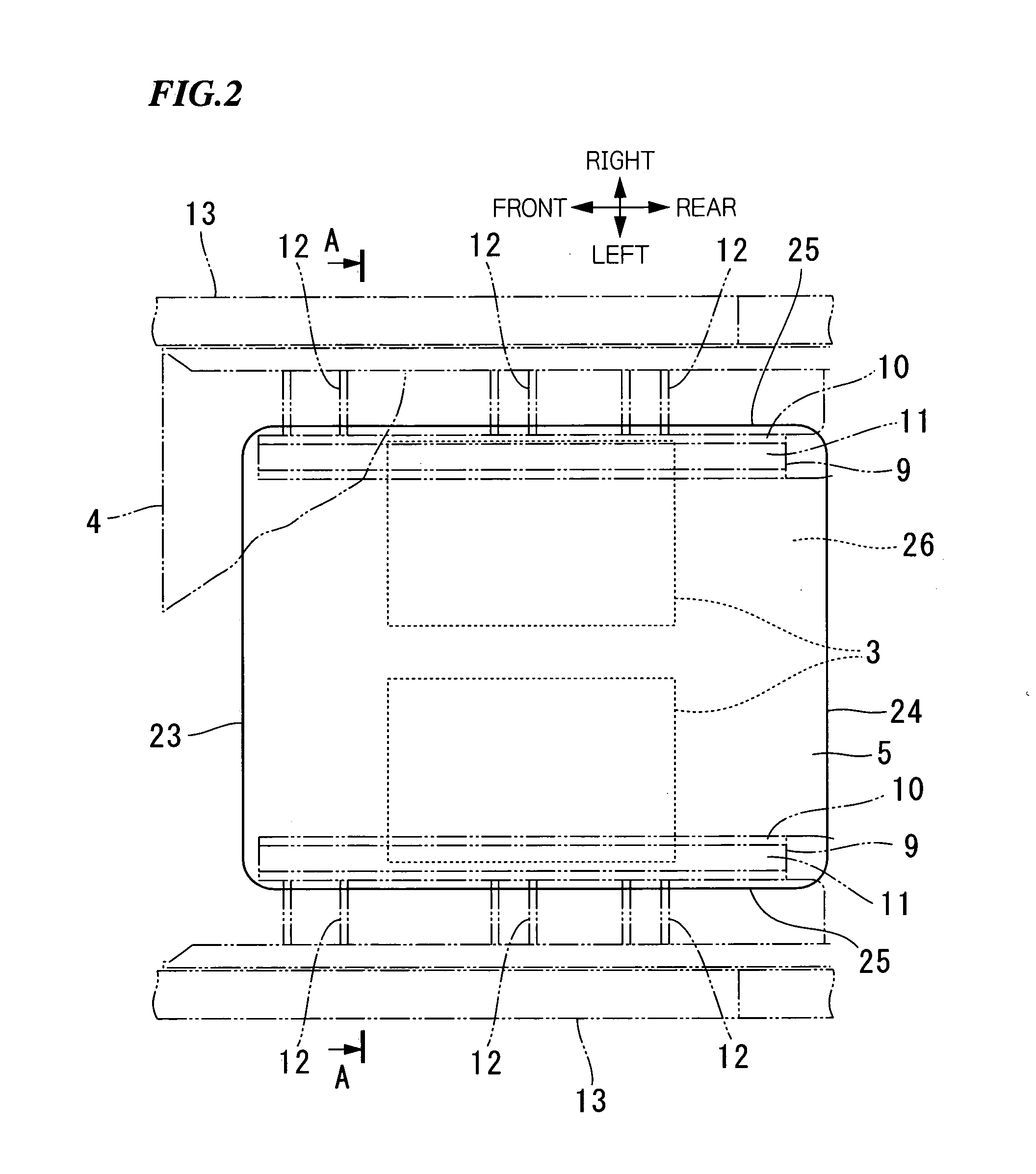
[0050] As shown in FIG. 2 and FIG. 3, the main frames 9 with a hat-like sectional form are joined via the flanges 10 to both the left and right sides of the bottom face of the front floor 4. The carbody skeleton 11 is formed in the longitudinal direction of the carbody with the main fra...

second embodiment

[0077] In the aforementioned second embodiment, the fuel cells 3 are supported by the front stack frame 231 and rear stack frame 232 provided in the widthwise direction of the vehicle on the bottom wall 226 of the box body 221 such that the fuel cells 3 are straddled by the side reinforcements 229. Accordingly, the fuel cells 3 are supported by the skeletal part 228 formed by the side reinforcements 229 in the longitudinal direction of the vehicle and by the skeletal part 235 formed by the front stack frame 231 and rear stack frame 232. Consequently, it is possible to reliably and stably fix the fuel cells 3 to the fuel cell system box 5.

[0078] With the aforementioned second embodiment, the sandwich panels 241 are connected so as to be straddled by the front stack frame 231 and rear stack frame 232 underneath the fuel cells 3, the spaces 240 are formed between the sandwich panels 241 and the bottom wall 226 of the box body 221, and these spaces 240 are filled with the anti-vibration...

third embodiment

[0102] With the third embodiment, hydrogen gas with lower specific gravity than air is measured by the hydrogen sensor 348 at the highest position inside the fuel cell system box 5 that is advantageous for measurement accuracy, with the result that measurement accuracy can be increased. In particular, as the hydrogen sensor 348 is positioned at the highest area in the bottom face of the lid 322, it is acceptable to use only one hydrogen sensor 348, and it is possible to bring about cost reductions compared to the case where a plurality of hydrogen sensors 348 are used.

[0103] In short, the effective height of the bottom face of the lid 322—that is, of the fuel cell system box 5—is adjusted by the first spacer S1, second spacer S2 and third spacer S3, with the result that hydrogen gas is gradually guided to the higher elevations of height H1, height H2 and height H regardless of the area where hydrogen gas exists, and that the hydrogen concentration is reliably and accurately measured...


PUM


Abstract

The fuel cell vehicle, includes a fuel cell generating electricity by an electrochemical reaction of hydrogen and oxygen; an accessory for the fuel cell; and a fuel cell system box mounted on a vehicle body and housing the fuel cell and the accessory, wherein the fuel cell system box is formed in a vessel shape which has a bottom wall, a first side wall, and a second side wall, the first side wall supporting at least one pipe through which a fluid supplied to the fuel cell flows, and the first side wall is constituted of a material having a specific gravity that is greater than that of the bottom wall and the second wall.

Description

BACKGROUND OF THE INVENTION [0001] 1. Field of the Invention [0002] The present invention relates to a fuel cell vehicle, and particularly to a fuel cell vehicle provided with anti-vibration measures in a fuel cell system box that houses fuel cells and the like, and to a fuel cell vehicle able to rapidly measure the hydrogen concentration inside the casing that houses the fuel cells and the like. [0003] Priority is claimed on Japanese Patent Application No. 2004-343118, filed on Nov. 26, 2004, Japanese Patent Application No. 2004-343120, filed on Nov. 26, 2004, Japanese Patent Application No. 2004-343121, filed on Nov. 26, 2004, Japanese Patent Application No. 2005-308407, filed on Oct. 24, 2005, Japanese Patent Application No. 2005-308508, filed on Oct. 24, 2005, and Japanese Patent Application No. 2005-311435, filed on Oct. 26, 2005, the contents of which are incorporated herein by reference. [0004] 2. Description of Related Art [0005] Fuel cell vehicles mounting fuel cells have p...

Claims


Application Information

Patent Timeline
Patent Type & Authority Applications(United States)
IPC IPC(8): B60K1/00
CPCB60K1/04B60K15/013B60K15/03006B60K15/063B62D21/16B62D25/20B62D25/2036H01M8/04089H01M8/2475H01M2250/20Y02T90/32Y02E60/50Y02T90/40
Inventor KATO, TAKASHIANAZAWA, MAKOTOKOYAMA, TAKATSUGUMATSUMOTO, MITSUNORINAKAARAI, MASATO
Owner HONDA MOTOR CO LTD
Why Eureka
Try Eureka