Exhaust purification system for internal combustion engine and control method of the exhaust purification system

a technology of exhaust purification system and internal combustion engine, which is applied in the direction of electric control, machines/engines, mechanical equipment, etc., can solve the problem of difficult accurate estimation of the optimum air-fuel ratio, and achieve the effect of reducing sox emissions

Inactive Publication Date: 2009-01-22
TOYOTA JIDOSHA KK
View PDF8 Cites 5 Cited by
  • Summary
  • Abstract
  • Description
  • Claims
  • Application Information

AI Technical Summary

Benefits of technology

[0006]The present invention provides an exhaust purification system for an internal combustion engine and a method of controlling the exhaust purification system, which allow a more accurate estimation of the optimum air-fuel ratio when the ratio is richer than the stoichiometric ratio.
[0017]In the exhaust purification system for an internal combustion engine according to the first aspect of the invention, when the air-fuel ratio is rich (as the air-fuel ratio decreases), the hydrogen concentration in the exhaust gas upstream of the catalytic converter increases more noticeably. Therefore, the detection of the hydrogen concentration in the exhaust gas with the upstream hydrogen concentration sensor disposed upstream of the catalytic converter in the engine exhaust system permits a more accurate estimation of the optimum air-fuel ratio, when the ratio is richer than the stoichiometric ratio.

Problems solved by technology

This makes the accurate estimation of the optimum air-fuel ratio more difficult.

Method used


Image

  • Exhaust purification system for internal combustion engine and control method of the exhaust purification system
  • Exhaust purification system for internal combustion engine and control method of the exhaust purification system
  • Exhaust purification system for internal combustion engine and control method of the exhaust purification system

Examples


Embodiment Construction

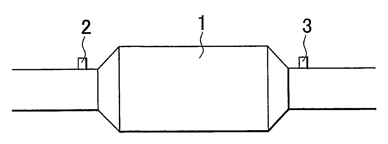
[0026]FIG. 1 is a schematic diagram of an exhaust purification system for an internal combustion engine according to one embodiment of the invention. A three-way catalytic converter 1 is disposed in the engine exhaust system. An upstream hydrogen concentration sensor 2 is disposed upstream of the three-way catalytic converter 1. A downstream hydrogen concentration sensor 3 is disposed downstream of the three-way catalytic converter 1.

[0027]In the embodiment of the invention, the internal combustion engine is predominantly designed to perform a homogenous combustion process with the stoichiometric ratio. The three-way catalytic converter 1 is designed to purity the exhaust gas burned at the stoichiometric ratio in a desired manner. However, under a high-load or high-speed operating condition, the air-fuel ratio may be enriched with respect to the stoichiometric ratio to increase engine output. Likewise, under a low-load or low-speed operating condition, the air-fuel ratio may be made...


PUM


Abstract

An exhaust purification system for an internal combustion engine has a hydrogen concentration sensor (2) disposed upstream of a catalytic converter (1) in the engine exhaust system to detect a hydrogen concentration in the exhaust gas. An optimum combustion air-fuel ratio is then estimated based on the detected hydrogen concentration.

Description

BACKGROUND OF THE INVENTION[0001]1. Field of the Invention[0002]The present invention relates to an exhaust purification system for an internal combustion engine and a control method of the exhaust purification system.[0003]2. Description of the Related Art[0004]As described in JP-A-H6-307271, an oxygen concentration sensor is disposed upstream of a catalytic converter in the engine exhaust system to detect an oxygen concentration in the exhaust gas and estimate the optimum air-fuel ratio based on the detected oxygen concentration.[0005]When the air-fuel ratio is leaner than the stoichiometric ratio (i.e., when the air-fuel ratio increases), the oxygen concentration in the exhaust gas increases more noticeably. This ensures a more accurate estimation of the optimum air-fuel ratio. However, when the air-fuel ratio is richer than the stoichiometric ratio, the oxygen concentration in the exhaust gas decreases to almost zero and then shows less noticeable change than the air-fuel ratio ...

Claims


Application Information

Patent Timeline
Patent Type & Authority Applications(United States)
IPC IPC(8): F01N3/00
CPCF01N11/00F01N2550/02F01N2560/02F02D41/0235Y02T10/22F02D41/1444F02D2041/147Y02T10/47F02D41/1441Y02T10/12Y02T10/40Y02A50/20
Inventor KATOH, KENJI
Owner TOYOTA JIDOSHA KK
Why Eureka
Try Eureka