The above discussed prior art problems and limitations are effectively remedied in the present invention of an improved
system for determining when a receiver is proximate to a wireless boundary encompassing and defined with reference to the location of a transmitter. The present invention is based on near-field
signal detection of the total power in a low-frequency (10 kHz to 100 kHz), quasi-static 3-axis magnetic field. Quasi-static magnetic fields are generally known to be immune to the field-strength variability problems that can occur in systems based on propagating RF fields because of multipath reflections and severe field
distortion by proximate conducting masses such as
body tissue. Operation in the near-field or quasi-static magnetic field zone is also generally known to be advantageous for wireless boundary
proximity detection because the sharp inverse 6th power proportionality of the magnetic field power with distance allows for more accurate range
thresholding decisions. The receiver module used to detect the magnetic field in the present invention is not required to transmit any signals and therefore can have lower cost and power, much longer battery life and simpler and more compact construction compared to prior art methods that require the portable device to transmit either an RF or ultrasonic signal. The receiver module in the present invention uses a novel single-output, two axis sensing antenna with orientation-independent response for detecting the total power in a 3-axis magnetic field signal. This provides for more accurate wireless boundary proximity
detection performance compared to prior art methods using only a single-axis sensing antenna. The present invention receiver module achieves accurate, orientation-independent
boundary detection using only one, non-multiplexed signal receiver circuit. This also allows for lower cost and power, longer battery life and simpler and more compact construction compared to prior art methods that can only achieve orientation-independent
boundary detection through the use of a multiplicity of single-axis sensing antennas and a corresponding multiplicity of receiver circuits.
The present invention uses a composite magnetic field which is continuously broadcast and detected with no time-sequential
multiplexing required for either the magnetic field signal generation, reception or detection. This allows for use of a magnetic
field detection process incorporating coherent filtering to advantageously reject interference signals associated with the power line frequency of either 50 or 60 Hz. This allows the present invention to be much less susceptible to common sources of
power line interference compared to prior art methods not incorporating rejection filtering of the power line frequency. In fact, coherent rejection filtering at the power line frequency is not possible for the prior art methods that require receiver antenna sequencing or
multiplexing. The present invention uses continuous, coherent binary
phase shift keying (BPSK) modulation signals to modulate a 3-axis magnetic field which is detected by a direct quadrature conversion receiver that translates the received signal directly into continuous, coherent quadrature I and Q
baseband components. This method of
carrier modulation and
down conversion allows for a lower effective
noise bandwidth in the post conversion filter compared to the
noise bandwidths of several kilohertz exhibited by prior art methods based on magnetic fields modulated in a time sequential fashion using on-off amplitude
keying or modulated using
differential phase shift
keying (DPSK) at rates in excess of 1 kHz. Additionally the use of
BPSK modulation is generally known to have theoretically superior intrinsic signal to noise and
bit error rate performance compared to DPSK. A lower receiver
noise bandwidth is advantageous for achieving better signal-to-noise ratio for the magnetic field measurement resulting in more accurate and higher resolution
boundary detection. The present invention uses
digital signal processing of the sampled
baseband signals to further improve the boundary detection accuracy compared to prior art methods that do not employ
digital signal processing. Because the sigma
delta modulators used for 9-bit (8 bits plus
sign bit) signal
digitization employ continuous time integration, the digital correlation filters used to process the
baseband data samples have a theoretical performance equivalent to ideal matched filters for extracting the signals from
random noise and for extracting the separately identifiable 3-axis magnetic field components from the composite received signal. Digital post
processing is also used to
advantage in the present invention for digitally combining the extracted measures of the 3-axis magnetic field components to form an orientation—independent digital measure of the total magnetic field power, and for additionally filtering the
power measure with a digital
moving average filter to achieve an overall
receiver system noise bandwidth on the order of 2 Hz.
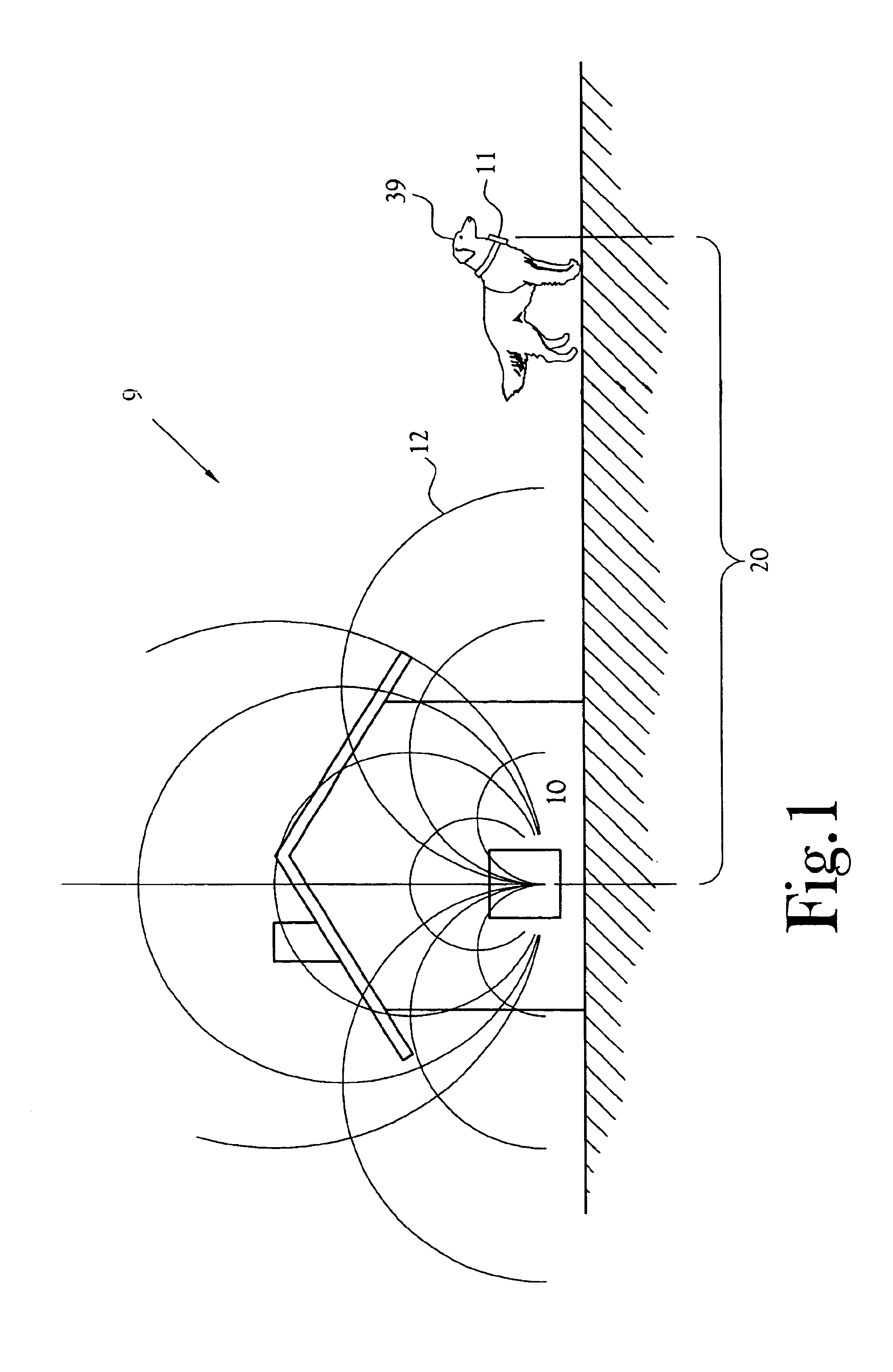
Compared to prior art methods, the present invention additionally provides means to detect when the magnetic field rapidly decreases due to a transmitter sudden failure or loss-of-power. In the case of a pet containment application, this prevents the pet from being shocked if the magnetic field transmitter is accidentally turned off or otherwise loses power. Compared to prior art methods, the present invention additionally provides means to detect when the received baseband signals are exceptionally noisy. In the case of a pet containment application, this feature is useful for preventing a
high magnetic field noise level, such as that encountered near an automobile engine, from being erroneously interpreted as a valid magnetic field power signal. Without this feature a pet may run into the street near the front of an automobile and not receive a correction because the detection device has no facility for distinguishing between a high level of magnetic field noise and a bona fide containment zone magnetic field signal. The present invention transmitter integrates all the signal generation circuitry onto a
CMOS integrated circuit chip and can therefore be lower cost and more compact compared to prior art methods that do not utilize a
single chip for all signal generation circuits. Similarly, the present invention receiver module integrates the entire signal receiving circuitry onto a
CMOS integrated circuit receiver
chip and can therefore be lower cost and more compact compared to prior art methods that do not use a single
integrated circuit receiver
chip. The receiver module also integrates all the
digital signal processing circuitry onto a digital
CMOS integrated circuit chip and therefore typically has lower cost and more compact compared to prior art methods that do not integrate all digital functions onto a
single chip or that implement the digital processing with a
general purpose microprocessor chip.
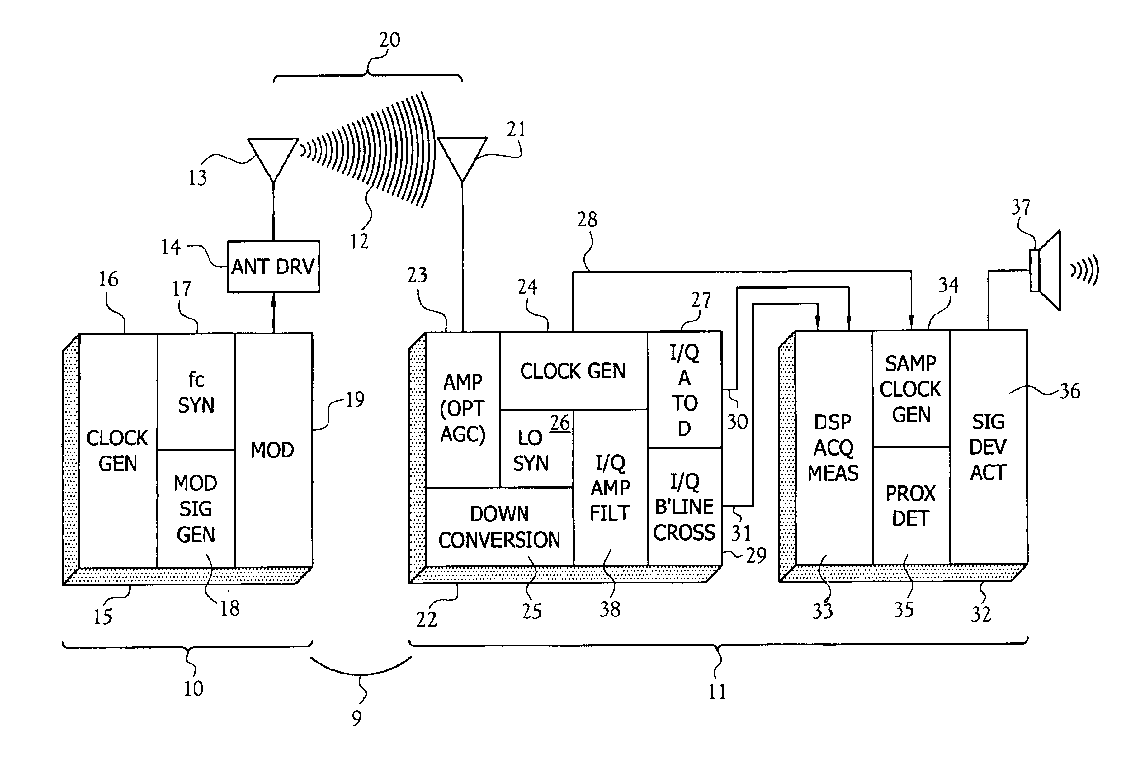
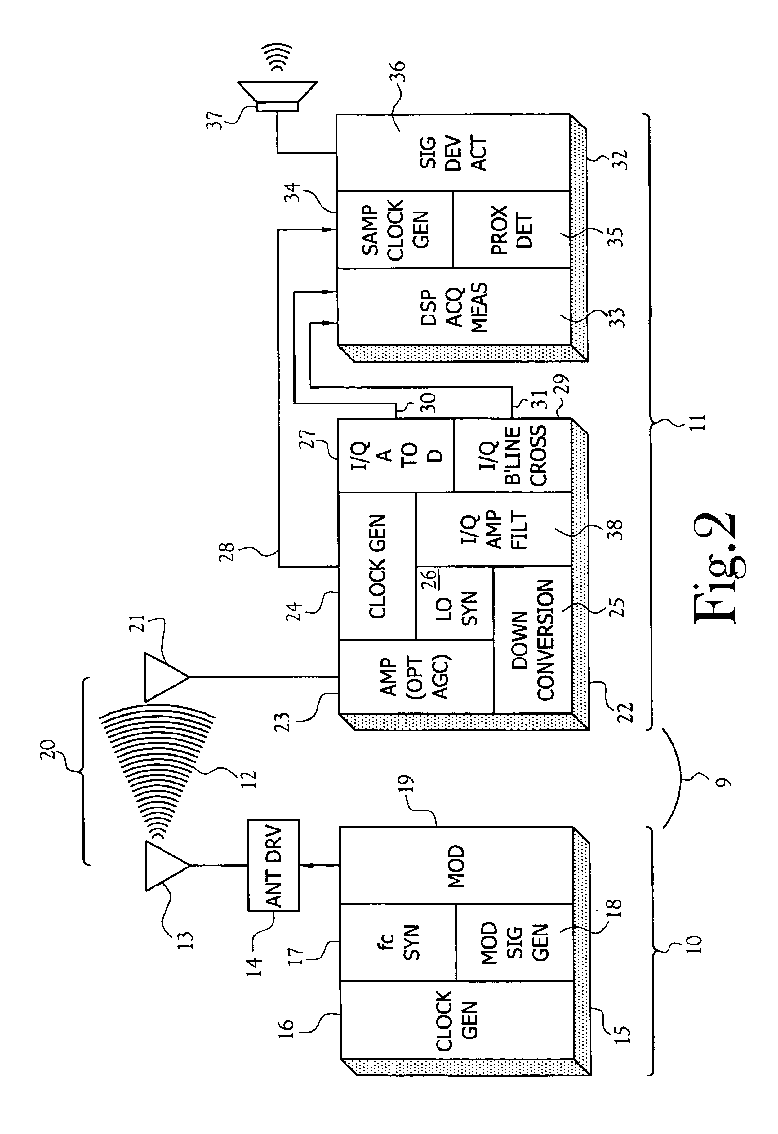
The transmitter employs means for continuously
broadcasting a 3-axis composite magnetic field having a single carrier frequency modulated using coherent binary
phase shift keying (BPSK). The CMOS signal generation chip is provided with a
master clock oscillator. Making the carrier frequency an integral multiple of the line
power frequency is advantageous for enabling the signal detection process to have a high degree of rejection of interference from the power line frequency or any of its significant
harmonics. A system
clock frequency of 32,760 Hz also allows the use of simple integral ratio frequency division for the generation of modulation waveforms having fundamental frequencies which are integral sub-
harmonics of the power line frequency. The 3-axis modulation signals are specifically chosen to facilitate a receiver module
digital signal detection process which has a high degree of rejection of interference at the power line frequency or any of its significant
harmonics and which allows accurate
decomposition of the composite received signal into separately identifiable components corresponding to the separately identifiable signals broadcast from each
transmitter antenna. To this end, a first modulation signal is a squarewave of
fundamental frequency equal to ¼ the power line frequency and the second and third modulation signals are orthogonal squarewaves of
fundamental frequency equal to ½ the power line frequency. Thus, each modulation signal exhibits zero cross-correlation with the power line frequency or any of its harmonics when cross-correlated over a full period of the first modulation signal. This property is advantageous for implementing device digital correlation filters that are highly effective for rejecting common sources of
electromagnetic power line interference signals. Also, a correlation waveform having fundamental squarewave frequency of ¼ the power line frequency (like the transmitter first modulation signal) exhibits zero cross-correlation with the transmitter second and third modulation signals when correlated over a
full cycle, irrespective of any particular
phase relationship between the correlation waveform and the signals. This property is advantageous for implementing simple and robust digital means for
phase locking the receiver module
data acquisition clock with the transmitter modulation signals. The magnetic field is broadcast from the transmitter with a 3-axis orthogonal antenna arrangement implemented with a total of four coils, each of identical construction for cost-efficient manufacture. The coils are mounted in a 3-dimensional configuration which may be enclosable by the smallest possible housing in a symmetric arrangement that effectively excludes any magnetic field cross-
coupling between the orthogonal antenna elements.
The receiver module is provided with a low-cost digital CMOS integrated circuit chip for processing the I and Q sigma
delta bit streams and baseline crossing countable pulse streams produced by the CMOS receiver chip. The digital circuit includes logic, memory,
digital filter and digital
arithmetic circuits for downsampling the sigma
delta I and Q bit streams to produce signed 8-bit I and Q data sampled at a rate nominally equivalent to 2× the power line frequency. The sampling rate
clock is obtained by integer division of the 32,760 Hz system clock where the division ratio is “dithered” to establish and maintain receiver module
phase locking with the phase of the transmitter modulation signals. The digital chip also provides digital correlation of 8 successive I and Q sampled data sets to extract sets of sample measures of the separately identifiable portions of the I and Q received baseband signals resulting from the separately identifiable magnetic
field intensity components broadcast by the transmitter first, second and third antennas. The 8-set correlations are clocked by a measurement rate clock which is the sampling clock divided by eight and therefore nominally ¼ the power line frequency. The correlations are done with a simple and compact digital addition or subtracting means whereby each I or Q data sample needs to be accumulated only once per measurement cycle. Although the correlations are done with simple digital means, the results match very closely with ideal continuous
time correlation since the sigma delta modulators employ continuous time integrators and the reference waveforms for
matched filter correlation are all symmetric, unit amplitude square
waves such that correlation by adding or subtracting is exactly equivalent to continuous
time correlation. In addition to providing nearly ideal
matched filter extraction of the separately identifiable magnetic field component measures, the correlation filters also provide, near ideal rejection of
power line interference components because the reference correlation waveforms are coherent and integral sub-harmonics of the power line frequency. Additionally, the correlation filtering process provides complete rejection of any dc components in the I and Q signal samples.
The digital chip also includes an 8-tap
moving average digital filter for improving the
signal to noise ratio associated with the total magnetic field
power measure. The power measures are initially computed at a measurement rate of nominally ¼ the power line frequency or 15 samples per second for the case of 60 Hz power. Thus the averaged
power measure from the
moving average filter is totally refreshed every 0.533 seconds, and the effective
noise bandwidth of the averaged data measurement is on the order of only 2 Hz.

