Method for Correcting a Wavelength and Tuning Range of a Laser Spectrometer

a laser spectrometer and wavelength correction technology, applied in the direction of instruments, spectrometry/spectrophotometry/monochromators, optical radiation measurement, etc., can solve the problem of inability to adjust the tuning range in the ongoing measurement operation using an etalon, the difference between the injection current and the wavelength is no longer proportional, and the problem of exacerbated problems

Active Publication Date: 2020-03-19
SIEMENS AG
View PDF4 Cites 1 Cited by
  • Summary
  • Abstract
  • Description
  • Claims
  • Application Information

AI Technical Summary

Benefits of technology

[0012]In view of the foregoing, it is therefore an object of the invention to make possible a correction of the wavelength and of the tuning range of a laser spectrometer applicable both in the case of direct absorption spectroscopy and also in the case of wavelength modulation spectroscopy, without having to take this out of the ongoing measurement operation or the measurement arrangement. This applies in particular to in-situ measurements, if the laser diode and the detector are accommodated, for example, in measurement heads installed at opposite points of a process gas line, or an exhaust gas duct.

Problems solved by technology

While the cuvette filled with the reference gas or reference gas mixture can remain in the laser spectrometer, in order, as explained above, to adjust the position of the reference absorption line in the detected absorption spectrum by way of the temperature of the laser diode during ongoing measurement operation, a readjustment of the tuning range in ongoing measurement operation using an etalon is not possible.
The problem is exacerbated when the laser diode is tuned over a very large range, so that the change in the injection current and that of the wavelength are no longer proportional to one another.

Method used


Image

  • Method for Correcting a Wavelength and Tuning Range of a Laser Spectrometer
  • Method for Correcting a Wavelength and Tuning Range of a Laser Spectrometer
  • Method for Correcting a Wavelength and Tuning Range of a Laser Spectrometer

Examples


Embodiment Construction

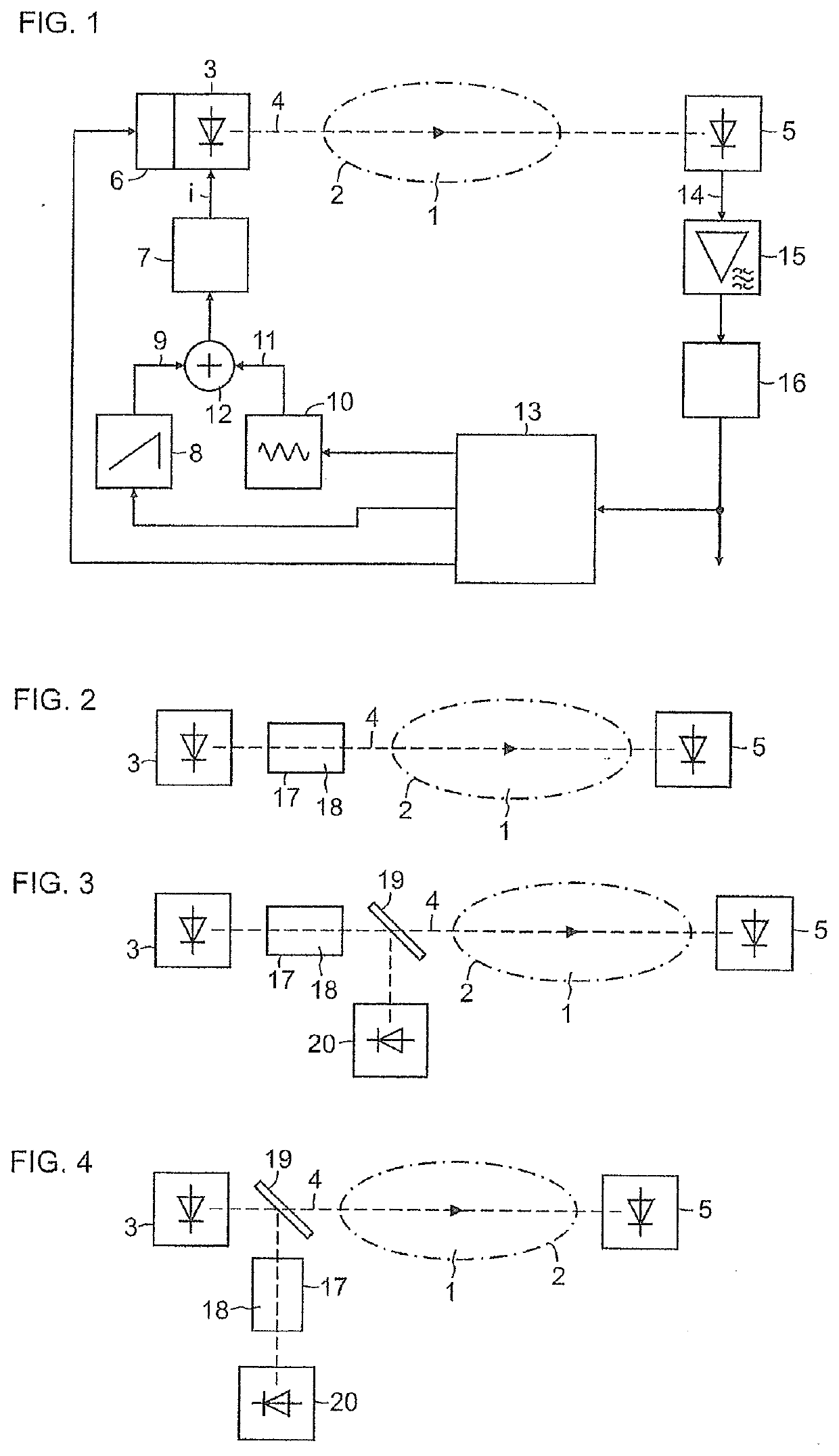
[0034]FIG. 1 shows an example of a laser spectrometer for measuring the concentration of at least one gas component of interest of a measurement gas mixture 1, which is contained in a measurement volume 2, for example, of a measurement cuvette or a process gas line. The spectrometer contains a laser diode 3, of which the light 4 falls through the measurement gas 1 onto a detector 5. The laser diode 3 is mounted on a temperature-regulated heat sink 6 and is driven by a controllable current source 7 with an injection current i. The intensity and wavelength of the created light 4 are dependent on the injection current i and the operating temperature of the laser diode 3. The current source 6 is driven periodically by a first signal generator 7 with a ramp-shaped current-time function (current ramp) 9, in order to sample a selected absorption line of a gas component of interest of the measurement gas mixture 1 with the correspondingly modulated light 4. The current-time function 9, as w...


PUM

PropertyMeasurementUnit
time-aaaaaaaaaa
absorption spectrumaaaaaaaaaa
temperatureaaaaaaaaaa

Abstract

A method for correcting a wavelength and a tuning range of a laser spectrometer in which the light from a wavelength-tunable laser diode, after being radiating through a gas, is detected and evaluated, wherein the laser diode is periodically driven with a current ramp, such that a time-resolved absorption spectrum of the gas is obtained upon the detection of the light, where in order to correct the wavelength and the tuning range of the laser spectrometer, a first step involves readjusting the central wavelength of the laser diode via the temperature thereof and based on the position of one of two different selected absorption lines in the detected absorption spectrum, and a second step involves correcting the tuning range of the laser diode via the gradient of the current ramp such that the spacing of the two absorption lines in the detected absorption spectrum remains constant.

Description

CROSS-REFERENCE TO RELATED APPLICATIONS[0001]This is a U.S. national stage of application No. PCT / EP2017 / 084448 filed Dec. 22, 2017. Priority is claimed on German Application No. 102016226215.7 filed Dec. 23, 2016 and EP Application No. 17150724 filed Jan. 9, 2017, the contents of which are incorporated herein by reference in their entirety.BACKGROUND OF THE INVENTION1. Field of the Invention[0002]The invention relates to a method for correcting the wavelength and the tuning range of a laser spectrometer, in which the light of a wavelength-tunable laser diode after radiating through a gas is detected and evaluated, wherein the laser diode is periodically driven with a current ramp, such that a time-resolved absorption spectrum of the gas is obtained upon the detection of the light, wherein in the absorption spectrum currently obtained, the actual position of an absorption line of the gas is compared with a target position of the same absorption line detected and stored in a precedin...

Claims


Application Information

Patent Timeline
Patent Type & Authority Applications(United States)
IPC IPC(8): G01J3/02G01J3/10G01J3/433G01N21/27G01N21/39
CPCG01J3/0297G01J2003/2866G01N2021/399G01N21/39G01J3/10G01N21/274G01J3/433G01N21/3504H01S5/0622G01J3/28G01J3/42H01S5/0612H01S5/06812H01S5/0683G01N2201/0231
Inventor DEPENHEUER, DANIEL
Owner SIEMENS AG
Why Eureka
Try Eureka