
Touch screen and manufacturing method thereof and touch display device

A touch screen and touch sensor technology, applied in the fields of touch screen and its manufacture, and touch display device, can solve the problem that users cannot see the touch screen information clearly, and achieve the effect of mature production process, improved effect and improved contrast ratio.

Inactive Publication Date: 2015-09-23
BOE TECH GRP CO LTD +1
View PDF3 Cites 15 Cited by
  • Summary
  • Abstract
  • Description
  • Claims
  • Application Information

AI Technical Summary

Problems solved by technology

[0003] The present invention provides a touch screen and its manufacturing method and a touch display device to solve or alleviate the problem that the user cannot clearly see the display in the touch screen due to the reflection of light by the touch screen when the touch screen is used under strong light in the prior art. technical issues of information

Method used


Image

  • Touch screen and manufacturing method thereof and touch display device
  • Touch screen and manufacturing method thereof and touch display device
  • Touch screen and manufacturing method thereof and touch display device

Examples


Embodiment 1

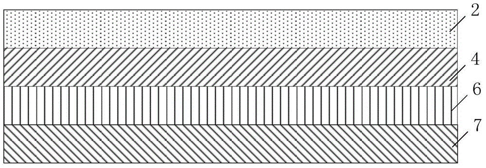
[0058] Embodiment 1 of the present invention firstly provides a touch screen, see figure 1 , which in turn includes:

[0059] Polarizing film 2, used to polarize incident light and transmit a component perpendicular to the touch screen;

[0060] The λ / 4 wave plate 4 is used to cause the incident light to produce a phase delay of λ / 4, it should be understood that here λ is the wavelength of the incident light;

[0061] polymer film 6; and

[0062] touch sensor7.

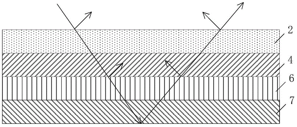
[0063] Among them, the combination of the polarizing film 2 and the 1 / 4 lambda wave plate (retardation film) 4 helps to reduce the reflection of ambient light and improve the use effect. figure 2 It is a schematic diagram of the reflection light path of the touch screen according to the embodiment of the present invention. The polarizing film 2 can be a polyvinyl alcohol PVA polarizing film, which is made of a PVA film layer after being dyed and stretched. The polarizing film 2 is the main part that forms polariz...

Embodiment 2

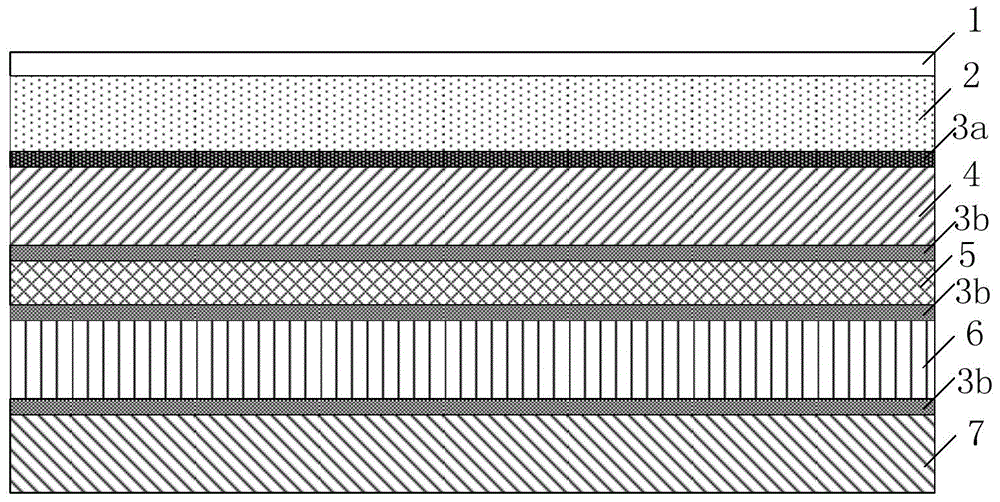
[0066] Embodiment 2 of the present invention is prepared on the basis of the touch screen shown in Embodiment 1 of the present invention, as image 3As shown, the surface of the polarizing film 2 may further include: a protective film 1 for anti-glare, anti-reflection and / or anti-static. The protective film 1 can be an anti-reflection triacetate protective film, and the TAC film layer with good optical uniformity and transparency is used to isolate moisture and air, so as to prevent the polarizing film 2 from losing its polarizing performance due to water absorption and fading, and at the same time, the protective film 1 can be protected. Treatments such as glare, anti-reflection, UV protection and / or antistatic coatings become functional protective films.

[0067] Optionally, between the λ / 4 wave plate 4 and the polymer film 6 may also include: a semi-transparent and semi-reflective metal shielding film 5, which may be a gold-plated film, a silver-plated film, an aluminum-pla...

Embodiment 3

[0072] Embodiment 3 of the present invention provides a touch display device, which includes a display screen and the touch screen as described in any one of the above items, wherein the touch screen is adhered to the display screen.

[0073] Optionally, the display screen may be an AMOLED display module.


PUM


Abstract

The invention provides a touch screen and a manufacturing method thereof and a touch display device. The touch screen orderly comprises a polarizing film for polarizing incident light, and transmitting the component vertical to the touch screen; a lambda / 4 wave plate for enabling the incident light to product phase delay of lambda / 4; a polymer film; and a touch sensor. The light path of the ambient light can be changed through the adoption of the polarizing film and the lambda / 4 film, the influence of the ambient light to the display effect of a display module is reduced; the contrast ratio is improved, the human eye viewing effect is improved, and the anti-reflection function of the touch screen is realized.

Description

technical field [0001] The invention relates to the field of display technology, in particular to a touch screen, a manufacturing method thereof, and a touch display device. Background technique [0002] Due to the structure and materials of the current touch screen products, when the touch screen is used under strong light such as the sun, the reflective screen will reflect the strong reflected light to the user's eyes, causing the user to be unable to see the information displayed on the touch screen. , and cause damage to the user's eyes. For this reason, in order to meet the needs of anti-reflection, anti-reflection film is generally used in the market at present, and this anti-reflection film needs to be pasted on the touch display screen of mobile phone display device. It can play an anti-reflection role to a certain extent, but since this anti-reflection film is pasted later, it not only affects the light transmittance of the screen, causes visual dimming and lower t...

Claims


Application Information

Patent Timeline
Patent Type & Authority Applications(China)
IPC IPC(8): G06F3/041
CPCG06F2203/04102G06F2203/04107G06F2203/04103G06F3/0412G06F3/041
Inventor 吴建杰陈丽莉董瑞君王晨如王光泉孙海威
Owner BOE TECH GRP CO LTD
Learn More