Network wiring system, bridge stand and removable distribution apparatus
A wiring device and network wiring technology, applied in electrical components, fiber mechanical structures, etc., can solve the problems of lack of flexibility and scalability in structural design, and achieve the effect of facilitating maintenance and expansion upgrades, maintenance and expansion.
- Summary
- Abstract
- Description
- Claims
- Application Information
AI Technical Summary
Problems solved by technology
Method used
Image

Examples
Embodiment 1
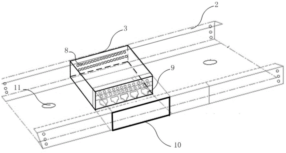
[0047] Based on the exemplary network cabling system of the present invention, this embodiment provides a specific bridge unit 2 and detachable wiring device 3 .
[0048] Such as image 3 As shown, the bottom of the bridge unit 2 is provided with rollers 21 ; the bottom of the detachable wiring device 3 is provided with guide rails 31 matching the rollers 21 .
[0049] When the guide rail 31 slides relative to the roller 21 , the detachable wiring device 3 enters and exits the window 10 to be loaded into or unloaded from the bridge unit 2 .
[0050] In order to prevent the detachable wiring device 3 loaded into the bridge unit 2 from squeezing the communication cables originally placed in the bridge unit 1, during specific implementation, the rollers 21 on the bottom of the bridge unit 2 should have a certain The height is so that a corresponding space is reserved between the detachable wiring device 3 loaded into the bridge unit 2 and the groove bottom of the bridge unit 2 f...
Embodiment 2
[0052] Based on the exemplary network cabling system of the present invention, this embodiment provides another specific bridge unit 2 and detachable wiring device 3 .
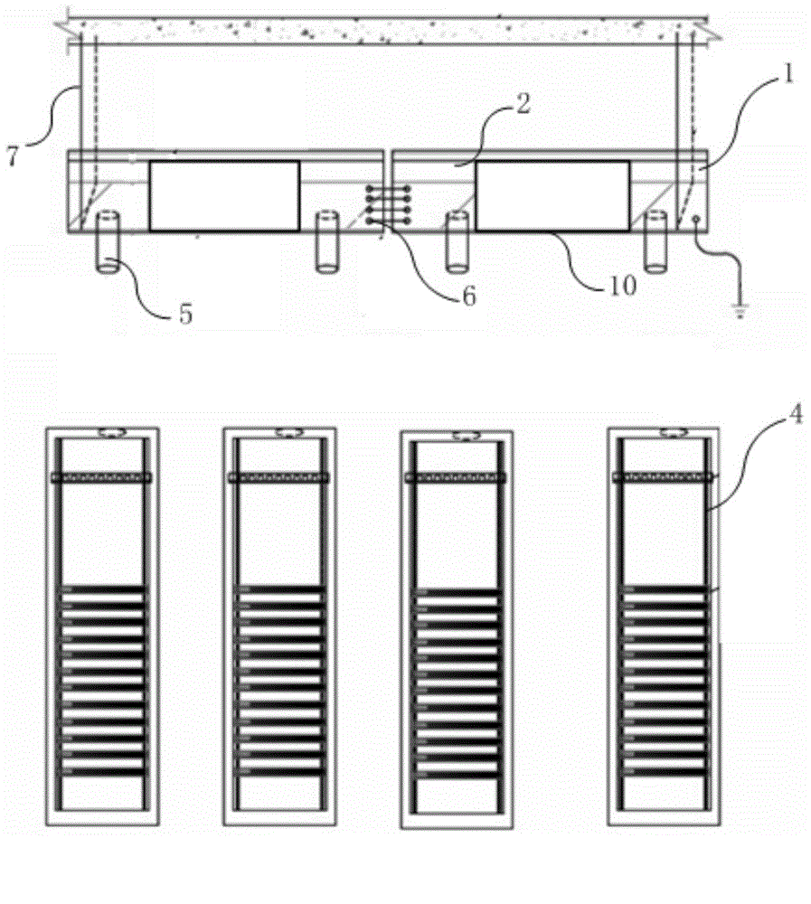
[0053] Such as Figure 4 As shown, the bottom of the detachable wiring device 3 is provided with rollers 32 ; the bottom of the groove of the bridge unit 2 is provided with guide rails 22 matching the rollers 32 .
[0054] When the rollers 32 slide along the guide rail 22 , the detachable wiring device 3 goes in and out of the window 10 to be loaded into or unloaded from the bridge unit 2 .
[0055] In order to prevent the detachable wiring device 3 loaded into the bridge unit 2 from squeezing the communication cables originally placed in the bridge unit 1, during specific implementation, the guide rail 22 on the bottom of the bridge unit 2 should have a certain The height is so that a corresponding space is reserved between the detachable wiring device 3 loaded into the bridge unit 2 and the groove bottom of...
Embodiment 3
[0057] Based on the exemplary network cabling system of the present invention, this embodiment provides another specific bridge unit 2 .
[0058] Such as Figure 5 As shown, a rotating baffle 23 is provided on the groove wall of the bridge unit 2 ; the rotating baffle 23 can rotate to cover or open the window 10 .
[0059] When the rotating baffle 23 covers the window 10, it can play the role of dustproof and beautiful appearance. When the rotating baffle 23 opens the window 10 , the detachable wiring device 3 can be conveniently loaded into the bridge unit 2 , or the detachable wiring device 3 can be removed from the bridge unit 2 .
[0060] Optionally, the rotating baffle 23 can be made transparent so as to observe the internal conditions of the bridge unit 2 , for example, it is convenient to observe the connection between the jumpers on the detachable wiring device 3 and the network interface 9 .
PUM
 Abstract
Description
Claims
Application Information
 - R&D
- Intellectual Property
- Life Sciences
- Materials
- Tech Scout
- Unparalleled Data Quality
- Higher Quality Content
- 60% Fewer Hallucinations
Browse by: Latest US Patents, China's latest patents, Technical Efficacy Thesaurus, Application Domain, Technology Topic, Popular Technical Reports.
© 2025 PatSnap. All rights reserved.Legal|Privacy policy|Modern Slavery Act Transparency Statement|Sitemap|About US| Contact US: help@patsnap.com