
Flexible mount for coupling force actuator to caliper jaw

A technology for mounting parts and actuators, which is applied in the direction of using electric/magnetic devices to transmit sensing components, using mechanical devices, instruments, etc., and can solve complex and expensive problems.

Active Publication Date: 2015-09-30
MITUTOYO CORP
View PDF15 Cites 1 Cited by
  • Summary
  • Abstract
  • Description
  • Claims
  • Application Information

AI Technical Summary

Problems solved by technology

However, the force sensing and indicating features of the caliper of the '009 publication may be considered "overkill" for many applications, and / or may be considered too expensive and / or complicated by many caliper users

Method used


Image

  • Flexible mount for coupling force actuator to caliper jaw
  • Flexible mount for coupling force actuator to caliper jaw
  • Flexible mount for coupling force actuator to caliper jaw

Examples


Embodiment Construction

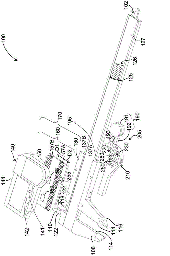
[0017] figure 1 is an exploded isometric view of hand tool style caliper 100 with flexible mount 205 for coupling force actuator assembly 190 to slider 130 with caliper jaws 116 and 118 . In this example, caliper 100 includes a slider displacement sensor 158 (eg, a magnetic or inductive sensor assembly) and a scale substrate 125 that includes a scale track 126 positioned in a groove 127 along elongated scale member 102 (FIG. excised sections of each are shown). It should be appreciated that in other implementations, other types of slider displacement sensors 158 (eg, capacitive, etc.) may be utilized. Slider assembly 170 includes electronics assembly 160 attached to slider 130 . Slider displacement sensor 158 is included in electronics assembly 160 . The general mechanical structure and physical operation of caliper 100 is similar to certain existing electronic calipers, such as that of commonly assigned US Patent No. 5,901,458, the entire contents of which are hereby incor...


PUM


Abstract

A flexible mount is provided for coupling a force actuator to a caliper jaw. The flexible mount includes a first mounting portion for being coupled to the caliper jaw, a second mounting portion for being coupled to the force actuator, and a flexible element (e.g., a parallel flexure) coupled between the first and second mounting portions. When a force is applied to the force actuator (e.g., by a user pushing on a thumbwheel) along the measuring axis direction, the flexible element flexes to generate a measuring force that is applied to the caliper jaw. The use of the flexible mount results in more control and a better feel for a user when attempting to exert control to provide a desired amount of force during a measuring process. The flexible mount may also utilize a fastening configuration that is compatible with existing mounting features on existing caliper jaws.

Description

technical field [0001] This invention relates generally to precision measuring instruments, and more particularly to calipers with movable jaws for measuring the dimensions of objects. Background technique [0002] Known calipers utilize pairs of pliers to determine measurements. The first clamp is typically fixed at one end of the metrological scale, while the second clamp is attached to a slider assembly that moves along the metrological scale. The outer dimensions of the object may be measured by placing the object between and on the inner surfaces of the first tong and the second tong. The inner dimensions of the object may be measured by placing the outer surfaces of the first and second tongs between and over inner surfaces (eg, hole walls) of the object. The slider assembly can be moved with the user's thumb, and a thumb wheel can be provided for controlled movement of the slider. One exemplary caliper utilizing a thumb wheel is described in US Patent No. 7,533,474...

Claims


Application Information

Patent Timeline
Patent Type & Authority Applications(China)
IPC IPC(8): G01B3/20
CPCG01B3/205G01B3/008G01B3/18G01B3/20G01B3/22G01B5/00G01B5/02G01B5/08G01B5/12G01B5/14G01D5/12
Inventor C.埃姆特曼M.E.戈兹沃西W.R.加里蒂
Owner MITUTOYO CORP
Learn More