Disc brake with parking function

A disc brake and functional technology, applied in the field of disc brakes, can solve problems such as difficult manipulation, restricted use of vehicle interior space, and large operating stroke.

Inactive Publication Date: 2007-03-28
HL MANDO CORP
View PDF1 Cites 52 Cited by
  • Summary
  • Abstract
  • Description
  • Claims
  • Application Information

AI Technical Summary

Problems solved by technology

[0006] For the traditional parking device of disc brake, the driver needs to pull the parking handle forcefully when parking, which makes the manipulation difficult and inconvenient
In addition, the conventional parking device requires the use of a parking handle (which occupies a large space in the car), and requires a large operating stroke, thereby restricting the use of the interior space of the vehicle

Method used


Image

  • Disc brake with parking function
  • Disc brake with parking function
  • Disc brake with parking function

Examples


Embodiment Construction

[0028] Reference will now be made in detail to embodiments of the invention, examples of which are illustrated in the accompanying drawings. The embodiments are described below to explain the present invention by referring to the figures.

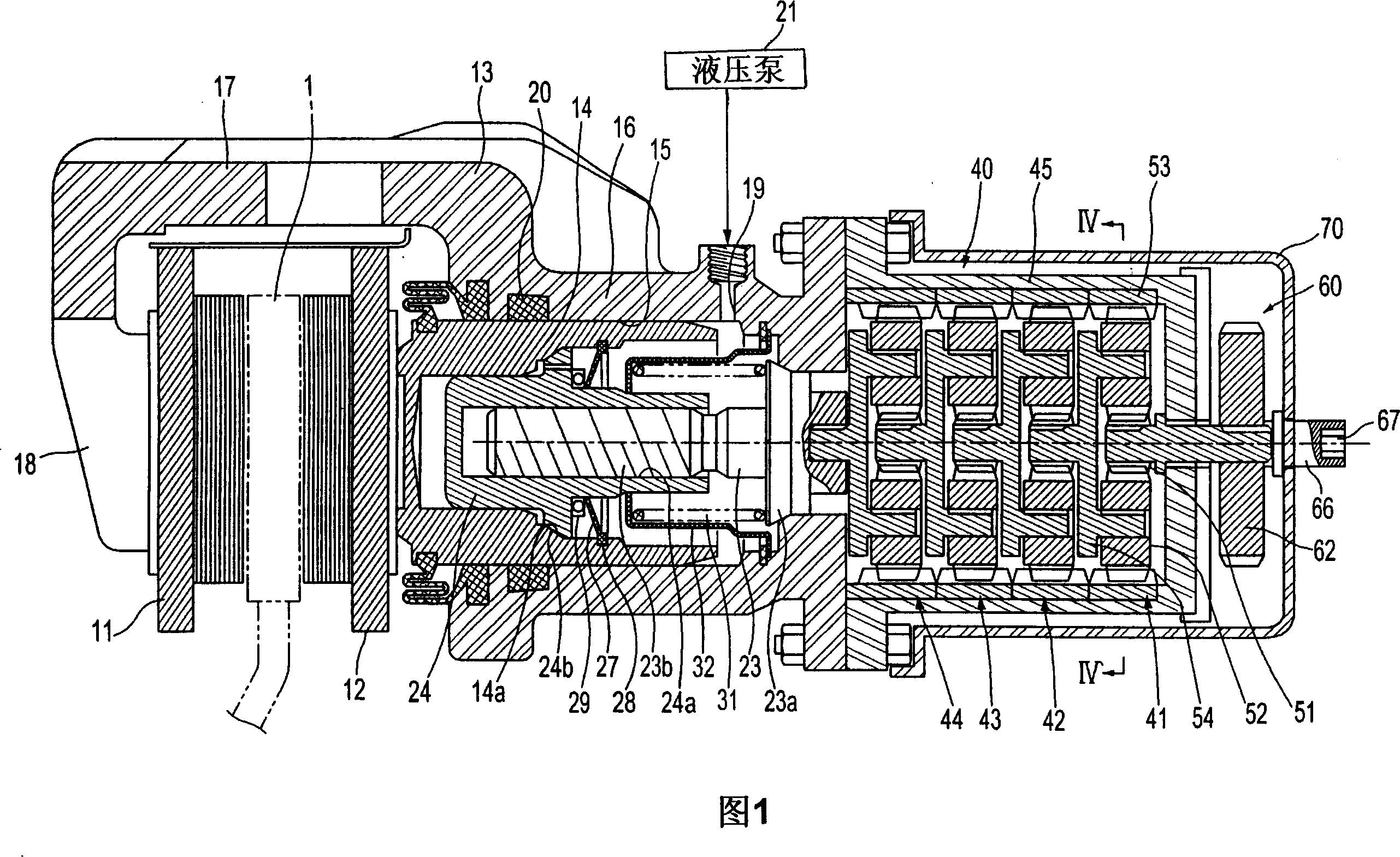
[0029] Referring to FIG. 1 , a disc brake according to the present invention includes first and second friction pads 11 and 12 arranged on both sides of a brake disc 1 that rotates with a wheel, a brake caliper housing 13 and a pressing friction pad 11 Piston 14 with 12.

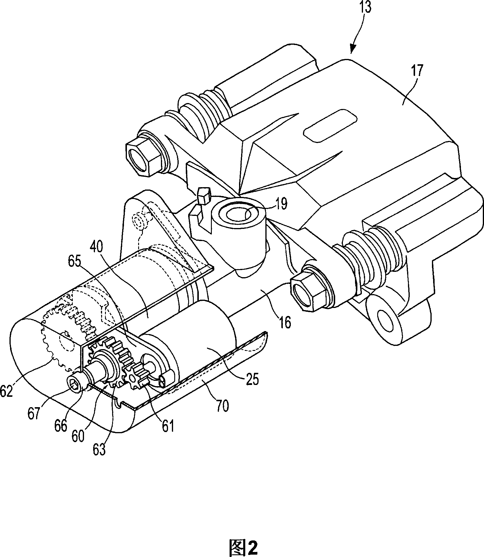
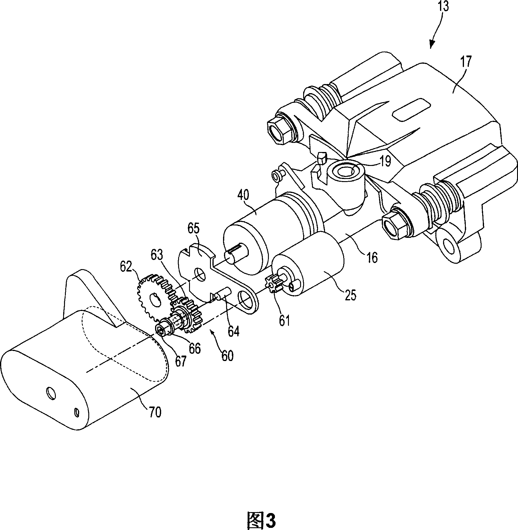
[0030] The caliper housing 13 includes: a main body 16 in which a cylinder portion 15 is formed to receive the piston 14 so that the piston 14 linearly moves therein; an extended connection portion 17 ; and a support portion 18 extending from the connection portion 17 to support the rear side of the first friction pad 11 . The main body 16 is formed with an oil port 19 through which brake oil flows into the cylinder portion 15 to apply hydraulic pressure for braking, an...


PUM


Abstract

A disc brake enables a parking apparatus to be operated via actuation of an electric motor, thereby permitting easy operation of the parking apparatus. The disc brake comprises a piston to compress a friction pad used for braking of a disc, a caliper housing to receive the piston such that the piston moves linearly therein, and having a cylinder section to which a hydraulic pressure for braking is applied, an actuation shaft rotatably installed within the cylinder section, and having a male screw formed thereon, a compression sleeve installed within the piston to compress or release the piston while linearly moving therein by rotation of the actuation shaft, and having a female screw formed thereon to engage with the male screw of the actuation shaft, an electric motor to rotate the actuation shaft, a multi-stage reduction gear train to transmit rotational force of the electric motor to the actuation shaft. The multi-stage reduction gear train has a central axis deviated from that of the electric motor, and a shaft connected with a shaft of the electric motor via a power transmission unit.

Description

[0001] Cross References to Related Applications [0002] This application claims priority from Korean Patent Application No. 2005-0088010 filed with the Korean Intellectual Property Office on Sep. 22, 2005, the disclosure of which is hereby incorporated by reference. technical field [0003] The present invention relates to a disc brake with a parking function, and more particularly, to a disc brake adapted to realize the parking function through the actuation of an electric motor. Background technique [0004] Disc brakes with a parking function for vehicles are known in the art. An example of the disc brake is disclosed in Japanese Patent Laid-Open Publication No. 2002-235779. The disc brake in this document has a typical hydraulic braking function and a parking function, wherein the hydraulic braking function is realized in such a way that the hydraulic pressure is established by the operation of the driver stepping on the brake pedal, and the hydraulic pressure makes th...

Claims


Application Information

Patent Timeline
Patent Type & Authority Applications(China)
IPC IPC(8): F16D65/34F16D55/224F16D55/225F16D65/14F16D65/18F16D65/54F16D121/24F16D125/40F16H1/46F16H57/021F16H57/023
CPCF16D2127/04F16D2121/02F16D2125/50F16D2123/00F16D2125/40B60T13/588F16D2121/24F16D65/18
Inventor 卢康星
Owner HL MANDO CORP
Why Eureka
Try Eureka