
Impedance matching method and impedance matching system for antenna

An impedance matching and antenna technology, applied in the field of communication, can solve the problems of destroying the impedance matching degree of the antenna, affecting the ability of the antenna to receive signals, and changing the antenna, so as to achieve the effect of ensuring performance.

Active Publication Date: 2015-09-30
上海东洲罗顿通信股份有限公司
View PDF5 Cites 9 Cited by
  • Summary
  • Abstract
  • Description
  • Claims
  • Application Information

AI Technical Summary

Problems solved by technology

However, when the antenna of the terminal is in contact with or close to other objects (such as human skin), the impedance of the antenna will change, thereby destroying the impedance matching degree of the antenna and affecting the ability of the antenna to receive signals

Method used


Image

  • Impedance matching method and impedance matching system for antenna
  • Impedance matching method and impedance matching system for antenna
  • Impedance matching method and impedance matching system for antenna

Examples


Embodiment Construction

[0030] In order to make the object, technical solution and advantages of the present invention clearer, various embodiments of the present invention will be described in detail below in conjunction with the accompanying drawings. However, those of ordinary skill in the art can understand that, in each implementation manner of the present invention, many technical details are provided for readers to better understand the present application. However, even without these technical details and various changes and modifications based on the following implementation modes, the technical solution claimed in each claim of the present application can be realized.

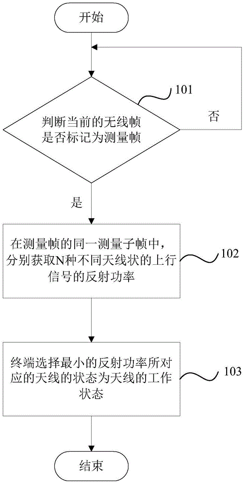
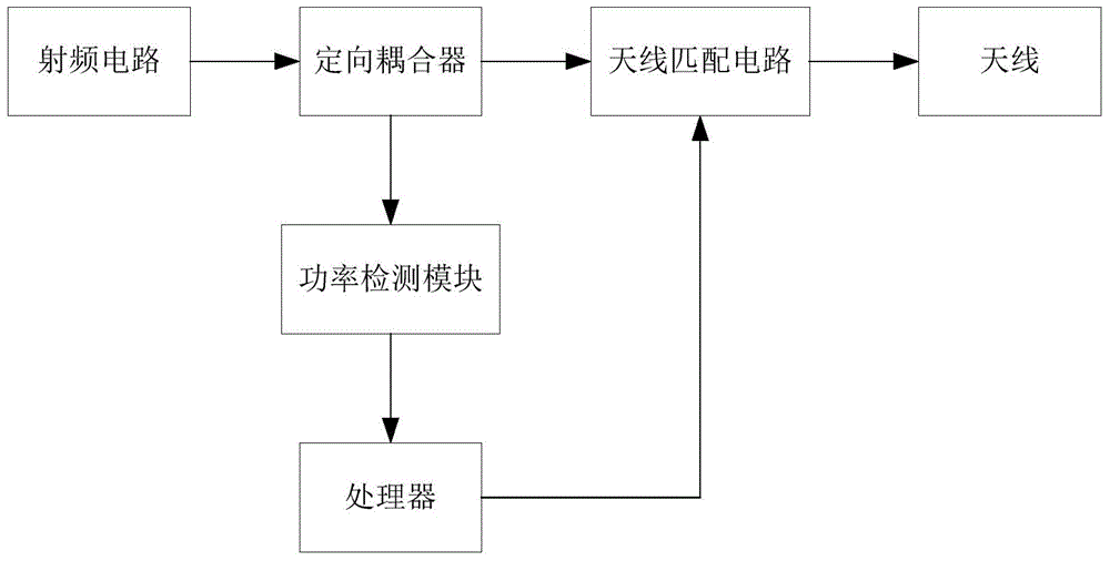
[0031] The first embodiment of the present invention relates to an impedance matching method of an antenna. The main idea of ​​this method is to judge the impedance matching degree between the radio frequency circuit and the antenna by calculating the reflected power of the antenna uplink signal, and adjust the impedance of ...


PUM


Abstract

The invention relates to the field of communication and discloses an impedance matching method and an impedance matching system. According to the impedance matching method, reflection power of upstream signals of N different antenna states is acquired respectively by a terminal in a same measuring subframe; then the antenna state corresponding to the minimum reflection power is selected as a working state of an antenna. Compared with the prior art, the impedance matching method has the advantages that the reflection power of the upstream signals of the antenna in different states are measured in a same measuring subframe, an impedance matching degree between a radio-frequency circuit and the antenna is judged, impedance of the antenna is adjusted according to the impedance matching degree, the minimum reflection power is selected, and the antenna state corresponding to the minimum reflection power is adopted as the working state of the antenna, so that performance of the antenna can be improved.

Description

technical field [0001] The present invention relates to the field of communications, in particular to an antenna impedance matching method and system based on a mobile terminal. Background technique [0002] In a mobile terminal, an antenna is often used to receive and transmit signals, and in the process of receiving signals by the antenna, whether the impedance matching between the antenna and the radio frequency circuit will directly affect the performance of the antenna for transmitting and receiving signals. [0003] Generally speaking, an antenna matching circuit is provided in the terminal, and the ability of the antenna to receive signals is ensured by performing impedance matching on the antenna. However, when the antenna of the terminal is in contact with or close to other objects (such as human skin), the impedance of the antenna will change, thereby destroying the impedance matching degree of the antenna and affecting the ability of the antenna to receive signals...

Claims


Application Information

Patent Timeline
IPC IPC(8): H04B1/40H04B17/30
Inventor 邵一祥
Owner 上海东洲罗顿通信股份有限公司
Learn More