Flow-control within a high-performance, scalable and drop-free data center switch fabric

A switching structure, flow control technology, applied in the field of computer networks, can solve problems such as lossy, high cost, non-determinism, etc.

Active Publication Date: 2015-09-30
JUMIPER NETWORKS INC
View PDF3 Cites 3 Cited by
  • Summary
  • Abstract
  • Description
  • Claims
  • Application Information

AI Technical Summary

Problems solved by technology

Proprietary switching fabrics can provide high performance, but can sometimes be more expensive, and in some cases can provide a single point of failure for the network
Off-the-shelf packet-based switching components can be cheaper, but can result in lossy, non-deterministic behavior

Method used


Image

  • Flow-control within a high-performance, scalable and drop-free data center switch fabric
  • Flow-control within a high-performance, scalable and drop-free data center switch fabric
  • Flow-control within a high-performance, scalable and drop-free data center switch fabric

Examples


example 1

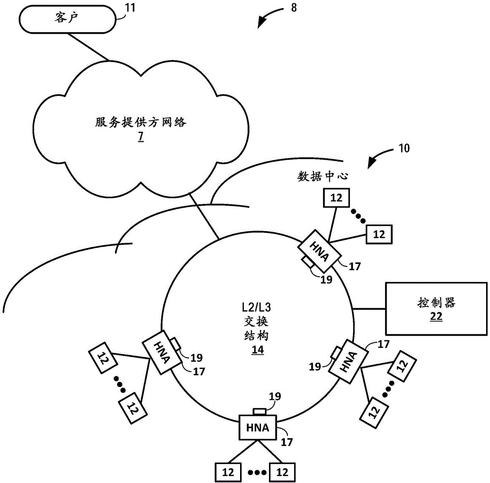
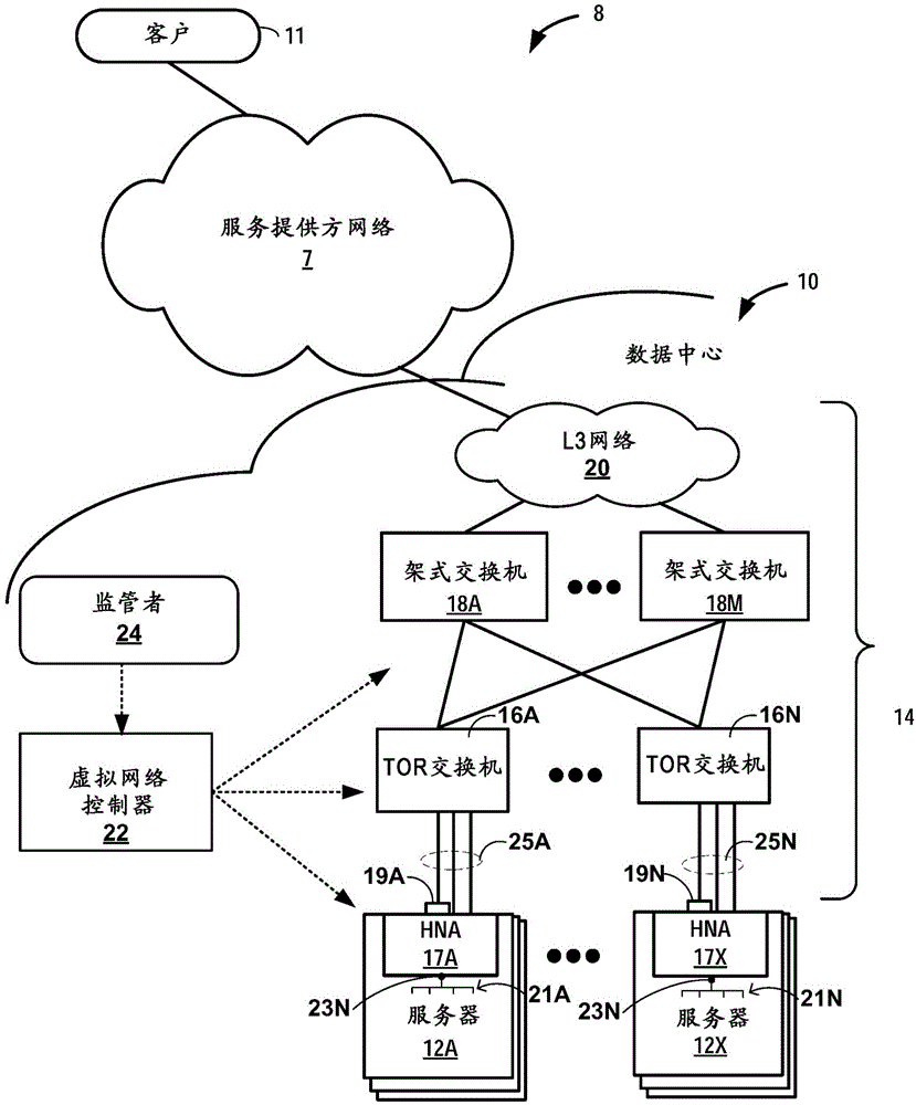
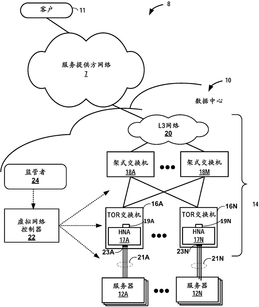
[0151] Example 1. A network system comprising: a switch fabric comprising a plurality of switches interconnected to form a physical network, wherein the switches provide connectionless, packet-based switching for packets through the switch fabric; A plurality of servers connected together, wherein each of the servers includes an operating environment executing one or more virtual machines communicating via one or more virtual networks; and a plurality of host network accelerators, the host network accelerators comprising : a hardware-based virtual router configured to extend one or more virtual networks to an operating environment of a virtual machine; and a flow control unit configured to be based at least on data to be transmitted by each of a plurality of host network accelerators To allocate bandwidth among multiple host network accelerators.

example 2

[0152] Example 2. The network system according to example 1, wherein the flow control unit is further configured to send the specified data to be sent to each of the other host network accelerators if the amount of data to be sent by the host network accelerator is non-zero Amount of queue length messages.

example 3

[0153] Example 3. The network system of example 2, each host network accelerator further comprising configuration data specifying a queue scale value, wherein the queue length message comprises a value scaled by the queue scale value to the specified amount of data.


PUM


Abstract

A high-performance, scalable and drop-free data center switch fabric and infrastructure is described. The data center switch fabric may leverage low cost, off-the-shelf packet-based switching components (e.g., IP over Ethernet (IPoE)) and overlay forwarding technologies rather than proprietary switch fabric. In one example, host network accelerators (HNAs) are positioned between servers (e.g., virtual machines or dedicated servers) of the data center and an IPoE core network that provides point-to-point connectivity between the servers. The HNAs are hardware devices that embed virtual routers on one or more integrated circuits, where the virtual router are configured to extend the one or more virtual networks to the virtual machines and to seamlessly transport packets over the switch fabric using an overlay network. In other words, the HNAs provide hardware-based, seamless access interfaces to overlay technologies used for communicating packet flows through the core switching network of the data center.

Description

[0001] Cross References to Applications [0002] This application claims the benefit of U.S. Provisional Application No. 61 / 973,045, filed March 31, 2014, the entire contents of which are hereby incorporated by reference. technical field [0003] The present invention relates to computer networks, and more particularly to data centers providing virtual networks. Background technique [0004] In a typical cloud-based data center, a large collection of interconnected servers provides computing and / or storage capacity for executing various applications. For example, a data center may include a facility that hosts applications and services for subscribers, such as customers of the data center. A data center may, for example, host all infrastructure equipment, such as networking and storage systems, redundant power supplies, and environmental controls. In most data centers, clusters of storage systems and application servers are interconnected via a high-speed switching fabric...

Claims


Application Information

Patent Timeline
Patent Type & Authority Applications(China)
IPC IPC(8): H04L12/713H04L12/801H04L12/917H04L45/586H04L47/52H04L47/30H04L47/76H04L47/80
CPCH04L47/52H04L47/805H04L47/30H04L47/10
Inventor P·辛胡
Owner JUMIPER NETWORKS INC
Why Eureka
Try Eureka