Novel diode lead gluing equipment
A sealing device and diode technology, applied to the surface coating liquid device, coating, etc., can solve the problems of lead wire production efficiency, large lead wire carrier volume, etc., to improve the overall production efficiency, facilitate logistics and processing Effect
- Summary
- Abstract
- Description
- Claims
- Application Information
AI Technical Summary
Problems solved by technology
Method used
Image

Examples
Embodiment 1
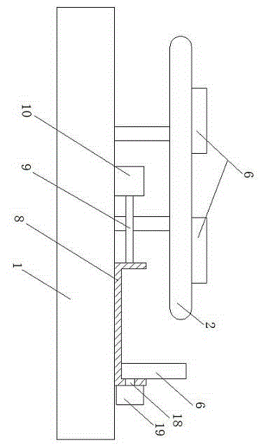
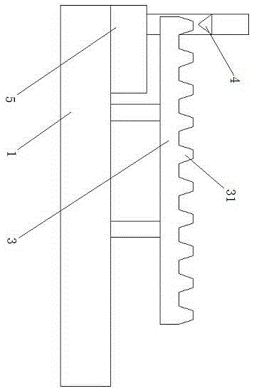
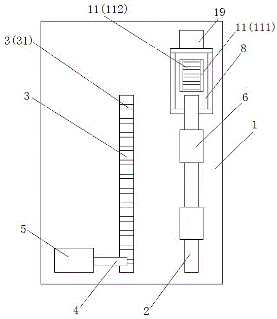
[0024] Such as figure 1 , figure 2 and image 3 A diode lead wire sealing device that can achieve uniform gluing is shown, which includes a support platform 1, a transmission chain 2 for transporting diodes is arranged on the support platform 1, and a sealing device for sealing the diode leads. The rubber rack 3 contains a plurality of upwardly extending sealing teeth 31, and the sealing rack 3 extends parallel to the transmission chain 2; the sealing rack 3 is provided with a glue port 4, which is connected to the glue groove 5 provided on the support platform 1 . The diode lead wire sealing device that can realize uniform gluing is provided with a lead wire placement end block 6, which is fixed on the transmission chain 2, and a plurality of lead wire placement end blocks 6 that are parallel to each other are provided with a plurality of lead wire placement holes 7. The axis of the lead wire placement hole 7 is extended perpendicular to the transmission chain 2; the corr...
Embodiment 2
[0035] As an improvement of the present invention, in the support bracket 11, the end positions of the two first support rods 111 away from the transmission chain are provided with an auxiliary support plate 17 extending vertically upward, and the auxiliary support plate 17 The height is 2 cm. With the above design, on the one hand, it can prevent the end block of the lead wire from moving to the outside of the support bracket due to its inertia, causing the end block of the lead wire to fall or even be damaged; When the supporting bracket connects with the lead wire placement end block and descends to the corresponding height of the collecting tank, the auxiliary support plate prevents the lead wire placement end block from sliding down during the flipping process of the support bracket connecting with the lead wire placement end block, causing its placement Misalignment occurs; the height limitation of the auxiliary support plate prevents it from affecting the lead placement...
Embodiment 3
[0038] As an improvement of the present invention, in the collecting tank 8, an adsorption pipeline 18 is arranged on the side surface away from the end of the transmission chain 2, which is connected to a vacuum adsorption pump 19 arranged outside the collecting tank 8; The adsorption pipe 18 extends above the inner wall of the collecting tank 8 . With the above-mentioned design, it can make the lead wire placement end block stably fixed on the side end surface of the collecting tank through the adsorption effect generated by the vacuum adsorption pump and the adsorption pipeline, so that multiple lead wire placing end blocks can be carried out in the collecting tank. It can maintain good stability when placed.
[0039] The remaining features and advantages of this embodiment are the same as those of Embodiment 2.
PUM
 Abstract
Description
Claims
Application Information
 - R&D
- Intellectual Property
- Life Sciences
- Materials
- Tech Scout
- Unparalleled Data Quality
- Higher Quality Content
- 60% Fewer Hallucinations
Browse by: Latest US Patents, China's latest patents, Technical Efficacy Thesaurus, Application Domain, Technology Topic, Popular Technical Reports.
© 2025 PatSnap. All rights reserved.Legal|Privacy policy|Modern Slavery Act Transparency Statement|Sitemap|About US| Contact US: help@patsnap.com