

A polishing jig with a circular arc scalpel blade
A scalpel and jig grinding technology, which is applied in the direction of manufacturing tools and other manufacturing equipment/tools, can solve the problems of low manual polishing efficiency, reduce processing progress, and labor consumption, so as to improve polishing processing efficiency and eliminate space occupation , high work efficiency
- Summary
- Abstract
- Description
- Claims
- Application Information
AI Technical Summary
Problems solved by technology
Method used
Image

Examples
Embodiment 1
[0055] Embodiment 1: A polishing jig with a circular arc scalpel blade
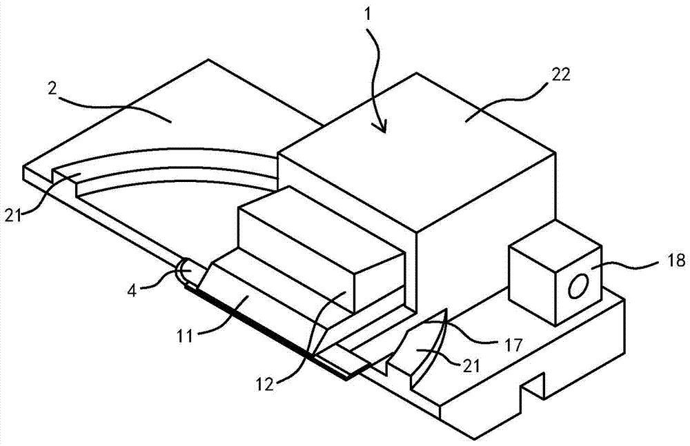
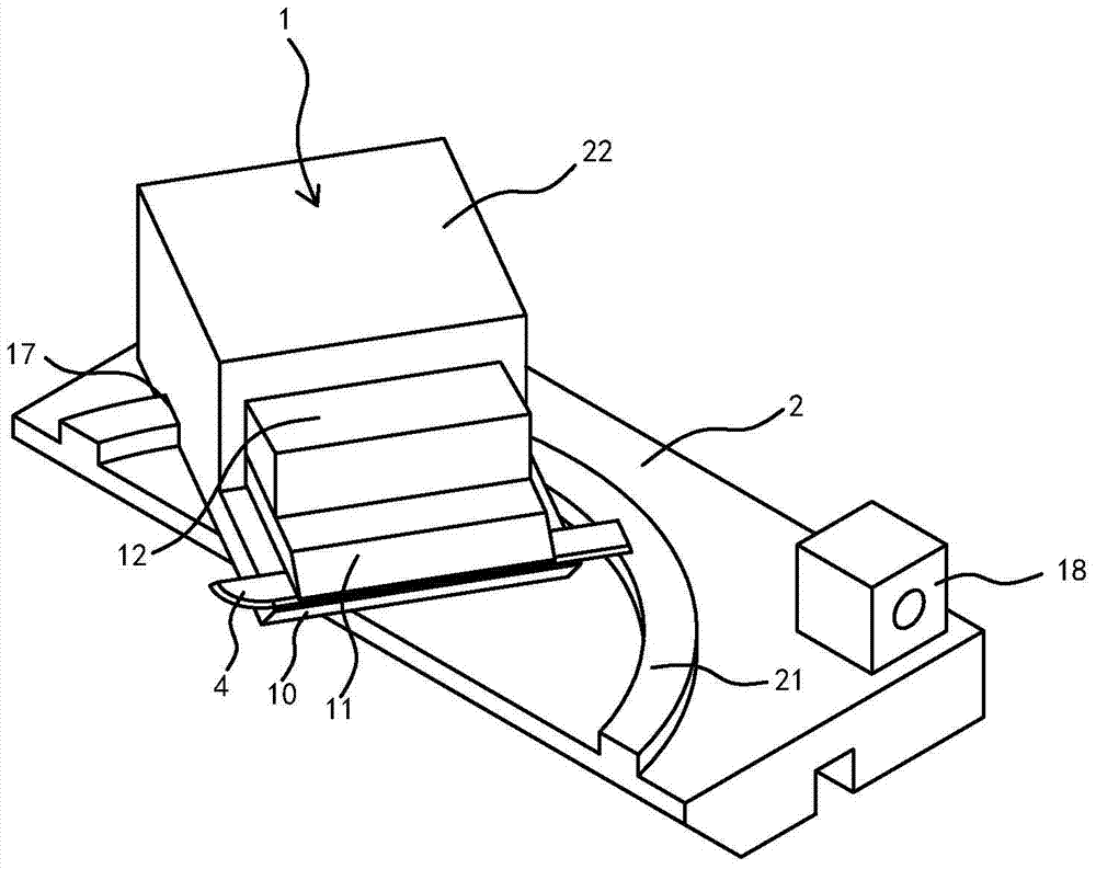
[0056] Such as Figure 1-2 As shown, the polishing fixture includes a knife holder 1 having a clamping mechanism for clamping a surgical blade 4 . The clamping mechanism has two working states: a clamping state and a loosening state. When in the clamping state, the clamping mechanism clamps the surgical blade 4 in the knife holder 1; when in the relaxed state, the clamping mechanism releases the surgical blade 4.
[0057] The polishing fixture also includes a track bottom plate 2 on which the tool holder 1 is placed. An arc-shaped track 21 and a matching body 17 matched with the arc-shaped track 21 are arranged between the track bottom plate 2 and the tool holder 1 . Such as Figure 1-2 As shown, in this embodiment, the arc-shaped track 21 is located on the track base plate 2, and the arc-shaped track 21 is convex, and the corresponding matching body 17 is a concave groove body at the bottom of the kn...
Embodiment 2
[0090] Embodiment 2: A polishing fixture with a circular arc scalpel blade
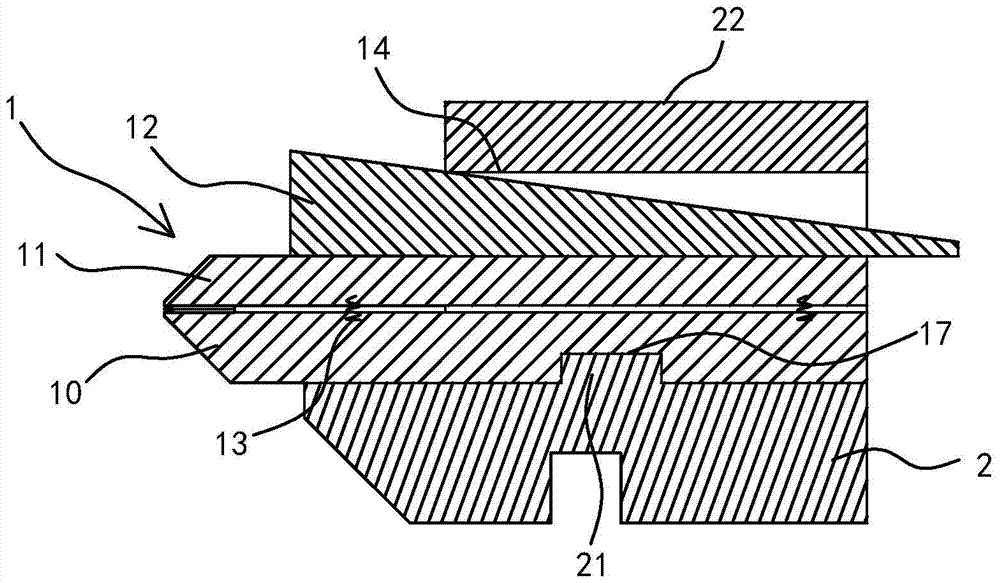
[0091] Such as Figure 5-6 As shown, the rest is the same as the first embodiment, the difference is that: the clamping mechanism includes a static clamping plate 10, and the static clamping plate 10 is fixed relative to the tool holder 1. A movable splint 11 is stacked on the static splint 10 , and a tension spring 15 acts on the movable splint 11 , and the tension spring 15 forces the movable splint 11 to move toward the direction close to the static splint 10 . A panel 12 is also provided between the static splint 10 and the movable splint 11, and there is an inclined-plane matching relationship between the panel 12 and the movable splint 11. It is inclined in the direction in which the panel 12 is embedded between the static splint 10 and the movable splint 11 .
[0092] Wherein, the slope matching relationship between the panel 12 and the movable splint 11 is composed of a sliding fit between t...
PUM
 Abstract
Description
Claims
Application Information