
Top plate for suspended ceiling

A roof and board technology, applied in covering/lining, building, building structure, etc., can solve the problems affecting the appearance and inconvenience

Inactive Publication Date: 2015-10-07
JIANGYIN DONGSHENG BUILDING MACHINERY
View PDF0 Cites 0 Cited by
  • Summary
  • Abstract
  • Description
  • Claims
  • Application Information

AI Technical Summary

Problems solved by technology

[0002] Ordinary suspended ceilings just tile the top plate to form a roof and then hang it on the ceiling. However, if you arrange the cables later, you need to split the top plate for wiring, which is very inconvenient, or the lines are directly exposed, but it affects the appearance.

Method used


Image

  • Top plate for suspended ceiling

Examples


Embodiment Construction

[0008] All features disclosed in this specification, or steps in all methods or processes disclosed, may be combined in any manner, except for mutually exclusive features and / or steps.

[0009] Any feature disclosed in this specification (including any appended claims, abstract and drawings), unless expressly stated otherwise, may be replaced by alternative features which are equivalent or serve a similar purpose. That is, unless expressly stated otherwise, each feature is one example only of a series of equivalent or similar features.

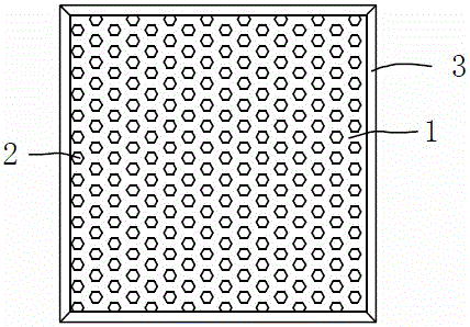
[0010] like figure 1 The top plate for a suspended ceiling shown includes a plate body 1, the surface of the plate body 1 is evenly distributed with ventilation holes 2, which is convenient for observation, and the inside of the plate body is kept ventilated and dry. Grooves are arranged around the edge of the plate body , there is a flip cover 3 on the tank body, and the flip cover 3 is connected to the board body 1. When wiring is required,...


PUM


Abstract

The invention discloses a top plate for a suspended ceiling. The top plate comprises a plate body. Vent holes are evenly distributed at the center of the plate body, and grooves are formed in the periphery of the plate body. When wires need to be distributed, the wires are distributed in the grooves, so that wiring is facilitated, and the integrated attractiveness cannot be affected by the wires.

Description

technical field [0001] The invention relates to a roof plate for a suspended ceiling, which belongs to the technical field of building decoration. Background technique [0002] Ordinary suspended ceilings just lay the top plate flat to form a roof and then hang it on the ceiling. However, if you arrange the cables later, you need to split the top plate for wiring, which is very inconvenient, or the lines are directly exposed, but it affects the appearance. Contents of the invention [0003] The invention relates to a roof plate for a suspended ceiling, which is convenient for later wiring. [0004] In order to achieve this purpose, the structure adopted in the present invention is: a roof plate for suspended ceiling, including a plate body, the plate body is evenly distributed with ventilation holes, and grooves are arranged on the periphery of the plate body, and each groove body There is a flap on the top. [0005] The beneficial effect is: when wiring is required, the...

Claims


Application Information

Patent Timeline
Patent Type & Authority Applications(China)
IPC IPC(8): E04F13/074
Inventor 王东平
Owner JIANGYIN DONGSHENG BUILDING MACHINERY
Learn More