
Detecting device and detecting method for pile foundation static load

A test device and static load technology, which can be used in foundation structure testing, foundation structure engineering, construction, etc., can solve problems such as limited weight, bracket deformation, working pile cracking or breaking, etc. Easy to implement, not easy to center of gravity, good measurement effect

Inactive Publication Date: 2015-10-14
朱洋
View PDF4 Cites 9 Cited by
  • Summary
  • Abstract
  • Description
  • Claims
  • Application Information

AI Technical Summary

Problems solved by technology

[0002] At present, the loading methods for static load tests of pile foundations include surcharge method or anchor pile method. The method of pile settlement test is to set up long-distance brackets to fix contact displacement sensors. Such loading and detection methods have the following problems : Due to the limited weight of the stacked pile and the difficulty in controlling the balance point of the piled load, it is not suitable for the static load test of large-tonnage pile foundations; because the anchor pile method uses the working piles around the test pile as anchor piles, once In the event of eccentric loading or overloading, there is a risk that the working pile will be cracked or broken; because the long-distance support is easily deformed by the influence of temperature, vibration, etc., it will cause problems such as insufficient accuracy of the settlement test or unreliable test data.

Method used


Image

  • Detecting device and detecting method for pile foundation static load
  • Detecting device and detecting method for pile foundation static load

Examples


Embodiment Construction

[0027] The embodiments of the present invention will be described in further detail below with reference to the accompanying drawings.

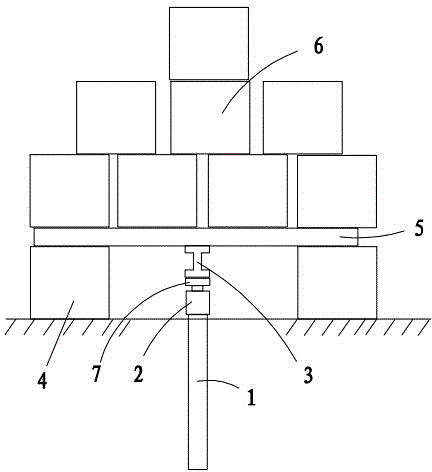
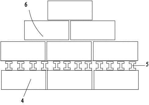
[0028] Figure 1 to Figure 2 Shown is a schematic diagram of the structure of the present invention.

[0029] The reference signs are: the tested pile foundation 1, the jack 2, the concentrated I-beam 3, the foot counterweight 4, the load-bearing I-beam 5, the pile counterweight 6, and the cushion block 7.

[0030] Such as Figure 1 to Figure 2 As shown,

[0031] A pile foundation static load test device, wherein: the test pile foundation static load device includes: jack 2, concentrated I-beam 3, stepping counterweight 4, load-bearing I-beam 5, and pressed pile counterweight 6; Jack 2 is placed on the top of the tested pile foundation 1, the center axis of the jack 2 and the tested pile foundation 1 are coincident, the stepping counterweight 4 is placed on both sides of the tested pile foundation 1, and the I-beam 3 is placed on the jack 2. Above...


PUM

PropertyMeasurementUnit
Pile diameteraaaaaaaaaa

Abstract

The invention discloses a detecting device for pile foundation static load. The detecting device comprises a lifting jack, force collecting I-shaped steel, foot-pad clump weights, force bearing I-shaped steel and press pile clump weights; the lifting jack is placed at the top of a to-be-detected pile foundation, the lifting jack is coincided with the central axis of the to-be-detected pile foundation, the foot-pad clump weights are placed on two sides of the to-be-detected pile foundation, the force collecting I-shaped steel is arranged above the lifting jack, the center of gravity of the force collecting I-shaped steel is located on the central axis of the lifting jack, the long edges of the force collecting I-shaped steel are parallel to the long edges of the foot-pad clump weights, the multiple force bearing I-shaped steel is arranged on the foot-pad clump weights, the press pile clump weights are arranged on the force collecting I-shaped steel, the number of the force collecting I-shaped steel is 1.2 times as much as the pile foundation design bearing capacity after the pile foundation design bearing capacity is divided by single weight of the press pile clump weights, and the press pile clump weights are stacked in a pyramid shape. The detecting device and a detecting method for the pile foundation static load have the advantages of being easy to carry, uneasy to deviate the center of gravity, safe and reliable and good in detecting effect.

Description

Technical field [0001] The invention relates to the technical field of civil engineering, in particular to a pile foundation static load test device and a test method thereof. Background technique [0002] At present, the loading method for static load test of pile foundation is stacking method or anchor pile method. The method for foundation pile settlement test is to set up a long-distance support to fix the contact displacement sensor. Such loading and detection methods have the following problems : Due to the limited weight of the stacking method and the difficulty of controlling the balance point of the stacking load, it is not suitable for the static load test of the large tonnage pile foundation; because the anchor pile method uses the working piles near the test pile as anchor piles, once In the event of eccentric load or overload, there is a danger of the working pile being cracked or broken; the long-distance support is susceptible to deformation due to the influence of...

Claims


Application Information

Patent Timeline
IPC IPC(8): E02D33/00
Inventor 朱洋
Owner 朱洋
Learn More