Novel glare-free LED lamp

An LED light, glare-free technology, applied in the field of lighting, can solve the problems of large distance and insufficient light irradiation range, and achieve the effects of low cost, wide light irradiation range and simple structure

Inactive Publication Date: 2015-10-14
郑华耀
View PDF0 Cites 2 Cited by
  • Summary
  • Abstract
  • Description
  • Claims
  • Application Information

AI Technical Summary

Problems solved by technology

However, most of the LED fluorescent lamps currently on the market have the following problems: The distance between the placement of the PCB light source module and the bottom of the bottom groove is large, so that the range of illumination is not wide enough

Method used


Image

  • Novel glare-free LED lamp
  • Novel glare-free LED lamp

Examples


specific Embodiment 1

[0018] Figure 1-Figure 2 constitute specific embodiments of the invention.

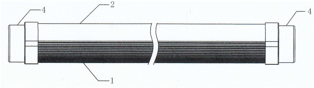
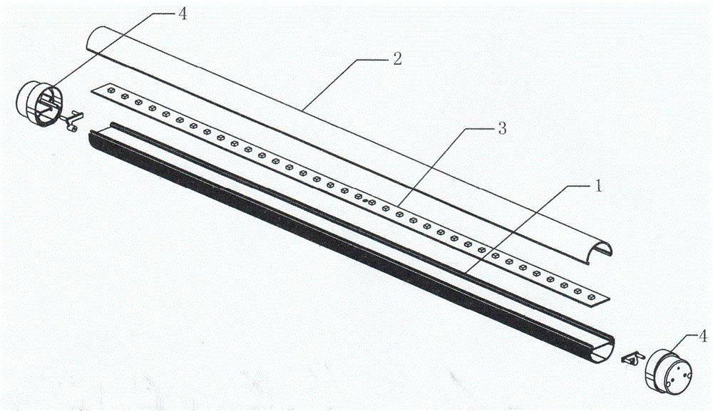
[0019] refer to figure 1 with figure 2 , this embodiment includes a bottom groove 1, a lampshade 2 and a light source plate 3 arranged in the lampshade, the bottom groove 1 and the lampshade 2 are fixedly connected to form a lamp body; the two ends of the bottom groove 1 are connected with lamp holders 4, and A plurality of LEDs are mounted on the light source board 3 .

[0020] In this embodiment, the cross-section of the lamp body formed by the fixed connection between the bottom groove 1 and the lampshade 2 is elliptical; the distance between the light source board 3PCB light source module and the bottom of the bottom groove 1 is 13.3 mm; the bottom groove 1 is made of silver-white anti-oxidation 6063 aluminum material; the lampshade 2 is made of milky white light-diffusing plastic PC material; the lamp holder 4 is made of milky white plastic PC material.


PUM


Abstract

The invention discloses a novel glare-free LED lamp. The novel glare-free LED lamp comprises a bottom groove, a lampshade and a light source panel arranged in the lampshade. The bottom groove and the lampshade are fixedly connected to form a lamp body. Lamp bases are connected to the two ends of the bottom groove. A plurality of LEDs are mounted on the light source panel. The novel glare-free LED lamp is wider in light-emitting range and irradiation range and has the advantages of being simple in structure, low in cost and durable, and the novel glare-free LED lamp can be widely used in various pubic places and suitable for mass production and application.

Description

technical field [0001] The invention relates to an LED lighting fixture, which belongs to the lighting field. Background technique [0002] Compared with traditional gas fluorescent fluorescent lamps, LED fluorescent lamps have the advantages of high luminous efficiency, low radiation, low power consumption, long life, low driving voltage, quick start, environmental protection, shock resistance and pressure resistance, and miniaturization of lamps. Therefore, LED fluorescent lamps have become Gradually replace traditional gas fluorescent fluorescent lamps. However, most of the LED fluorescent lamps currently on the market have the following problems: The distance between the placement of the PCB light source module and the bottom of the bottom groove is large, so that the irradiating range of the light is not wide enough. Contents of the invention [0003] The purpose of the present invention is to solve the above-mentioned problems of the prior art, and provide a PCB lig...

Claims


Application Information

Patent Timeline
Patent Type & Authority Applications(China)
IPC IPC(8): F21S2/00F21V23/00F21Y101/02
CPCF21V3/062F21Y2103/00
Inventor 郑华耀
Owner 郑华耀
Why Eureka
Try Eureka