Missile wing single side wing face folding mechanism

A technology of folding mechanism and elastic wings, which is applied to projectiles, offensive equipment, weapon types, etc., can solve the problems of large occupation space and high deployment synchronization, achieve small installation space, small transmission clearance and joint movement clearance, and save ammunition. The effect of body space utilization

Active Publication Date: 2015-10-14
JIANGXI HONGDU AVIATION IND GRP
View PDF9 Cites 10 Cited by
  • Summary
  • Abstract
  • Description
  • Claims
  • Application Information

AI Technical Summary

Problems solved by technology

This kind of mechanism has high synchronization but takes up too much space. For missiles with fixed wing surface and folded wing surface or small and medium-sized missiles with limited space for wing installation, this kind of mechanism will not be able to meet the requirements of use, and dual power sources are required. The left and right wings are driven separately to complete the requirements for the left and right wings to be deployed in place

Method used


Image

  • Missile wing single side wing face folding mechanism
  • Missile wing single side wing face folding mechanism
  • Missile wing single side wing face folding mechanism

Examples


Embodiment Construction

[0016] The present invention will be further described below in conjunction with the accompanying drawings and specific embodiments. The following examples are only used to illustrate the present invention, and are not intended to limit the protection scope of the present invention.

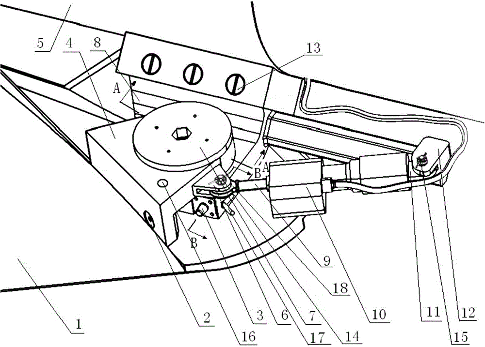
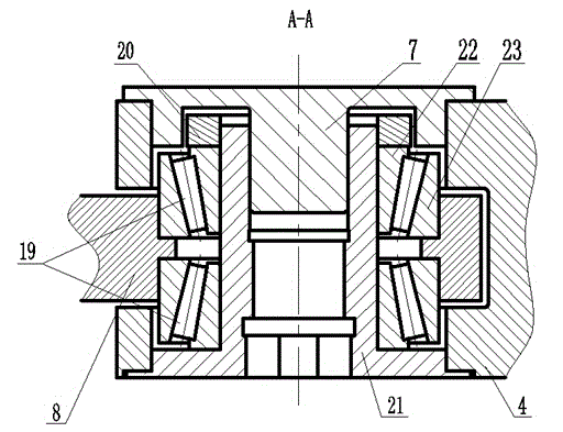
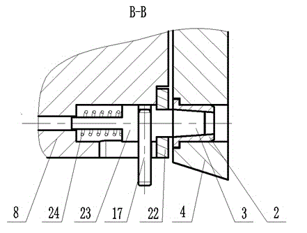
[0017] figure 1 As shown, the wing single-side wing surface folding mechanism of the present invention includes an adapter 8, a wing joint 4, a bearing 19, a wing rotating shaft 21, a pre-tightening nut 20, a tightening nut 7, an actuating device 10 and a spring locking pin 3. The adapter 8, the wing joint 4 and the bearing 19 are assembled into a revolving pair through the wing shaft 21, the pre-tightening nut 20 and the fastening nut 7. The body 5 is connected by bolts, and the connection points and the number of connecting bolts can be adjusted according to the load conditions of different missile wings. The wing joint 4 is integrally formed with the wing 1 or connected to the wing 1 by faste...


PUM


Abstract

The invention discloses a missile wing single side wing face folding mechanism which comprises a through-connection connector, a missile wing connector, bearings, a missile wing rotary shaft, a pretightening nut, a fastening nut, an actuating device and a spring locking pin. The through-connection connector, the missile wing connector and the bearings are assembled into a rotary pair through the missile wing rotary shaft, the pretightening nut and the fastening nut. The wing face folding mechanism is connected with a missile through the through-connection connector. The missile wing connector and a missile wing are integrally formed or connected through fasteners. The actuating device transmits power to the missile wing connector through a lug piece on the missile wing connector, so that the missile wing connector is made to drive the missile wing rotary shaft and inner rings of the springs to rotate around outer rings of the springs; when unfolding is conducted in place, the missile wing connector is locked through the spring locking pin, and the missile wing is locked. The missile wing single side wing face folding mechanism is modular, simple and reliable in structure and convenient to dismount and mount; mounting space occupied by modules is small, and the space utilization rate of the missile is saved; a transmission clearance and a joint movement clearance are small, and the transmission efficiency of the mechanism is high; the missile wing single side wing face folding mechanism can be applied to multiple missile wing folding and unfolding mechanisms in linear missile wing layout through refitting.

Description

technical field [0001] The invention relates to a wing-folding mechanism, in particular to a single-side wing-surface folding mechanism for a wing. Background technique [0002] At present, most of the folding wings of the one-wing layout at home and abroad are folded longitudinally, and the wing surfaces are symmetrically or cross-distributed. A single power source is used to deploy the two wings in place through a connecting rod or gear expansion mechanism. This kind of mechanism has high synchronization but takes up too much space. For missiles with fixed wing surface and folded wing surface or small and medium-sized missiles with limited space for wing installation, this kind of mechanism will not be able to meet the requirements of use, and dual power sources are required. The left and right bomb wings are driven separately to complete the requirement of the left and right bomb wings being deployed in place. [0003] Therefore, it is necessary to provide a new technica...

Claims


Application Information

Patent Timeline
Patent Type & Authority Applications(China)
IPC IPC(8): F42B10/14
Inventor 邓进陈雷孙英超蒋斌林黄海龙张耀庆王韬董皓葳
Owner JIANGXI HONGDU AVIATION IND GRP
Why Eureka
Try Eureka