Unlock instant, AI-driven research and patent intelligence for your innovation.

Pilot-based Joint Estimation Method of Departure Angle of Arrival for 3D Massive Antenna System

A large-scale antenna and joint estimation technology, applied in the field of communication, to achieve the effect of low complexity, time and resource saving

Inactive Publication Date: 2017-08-11
BEIJING INSTITUTE OF TECHNOLOGYGY
View PDF3 Cites 0 Cited by
  • Summary
  • Abstract
  • Description
  • Claims
  • Application Information

AI Technical Summary

Problems solved by technology

Applying this method, the problem of joint DOD and DOA estimation in such complex systems can be solved
[0007] The object of the method of the present invention is to solve the problem of joint DOD and DOA estimation of complex systems under the condition of satisfying a certain accuracy rate

Method used


Image

  • Pilot-based Joint Estimation Method of Departure Angle of Arrival for 3D Massive Antenna System
  • Pilot-based Joint Estimation Method of Departure Angle of Arrival for 3D Massive Antenna System
  • Pilot-based Joint Estimation Method of Departure Angle of Arrival for 3D Massive Antenna System

Examples


Embodiment

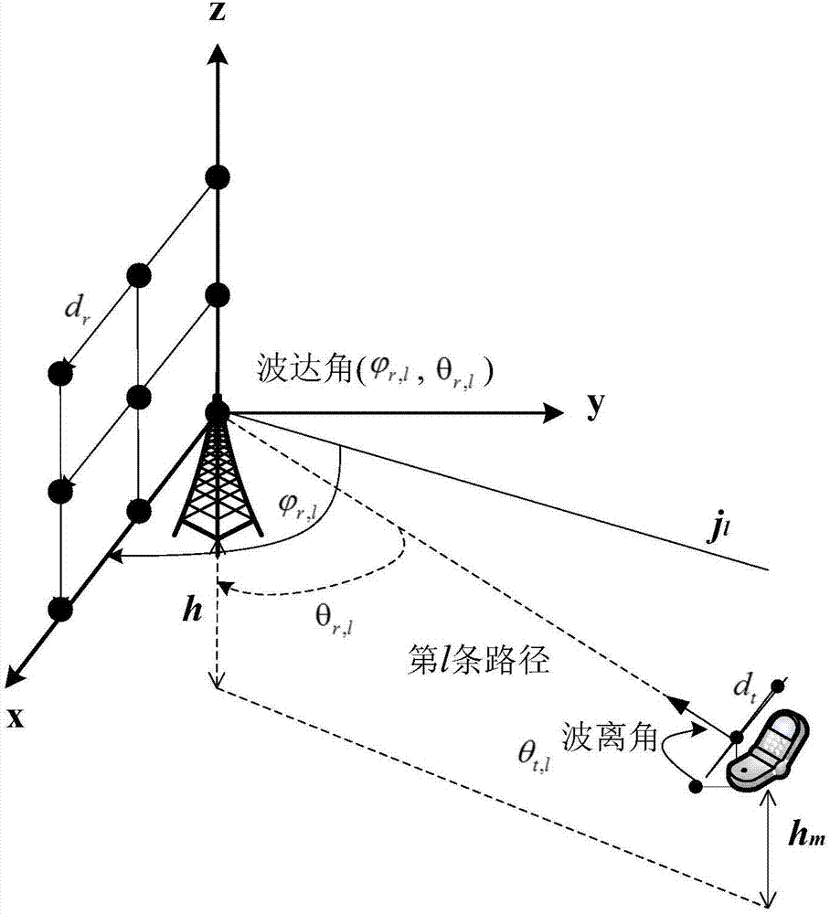
[0031] as attached figure 1 Shown is a schematic diagram of the three-dimensional large-scale network uplink transmission model selected for this embodiment, and d in the figure r and d t Respectively represent the array element spacing of the receiving antenna and the transmitting antenna element, h m and h represent the heights of the mobile terminal antenna and the base station antenna to the ground level, respectively. Taking the plane where the base station antenna is located as the reference plane, the projection of the line connecting the first path between the base station and the mobile terminal on the reference plane is j l , then define j l the angle with the x-axis is the azimuth angle of the arrival angle of the transmission path, and the included angle θ between the connection line of the first path of the base station and the mobile terminal and the opposite direction of the z-axis r,l is the pitch angle of the arrival angle of the transmission path, calle...


PUM


Abstract

The invention relates to a method for jointly estimating an angle of arrival and an angle of departure based on a pilot in a three-dimensional large-scale antenna system, and belongs to the technical field of wireless communication. The mobile end of the present invention uses a uniform linear antenna array to continuously send known pilot signals on each transmitting antenna, and the base station uses a uniform rectangular antenna array to record the fading loss of different paths according to the received signal, and estimate the entire system according to the least square estimation algorithm The equivalent channel gain H of H; the base station performs singular value decomposition on H to obtain singular values; the base station reorders the singular values ​​according to the fading loss order of different paths, and the reordered singular values ​​are the channel fading coefficients D of different paths; The base station estimates the angle of arrival of the receiving antenna according to the ESPRIT algorithm to obtain the receiving antenna array response A; the base station calculates the obtained H, D and A according to the formula H=ADB T Obtain the wave departure angle of the transmitting antenna array, that is, the transmitting antenna array response B. Compared with the prior art, the method of the invention has low complexity and saves time and resources.

Description

[0001] Technical field: [0002] The present invention relates to a pilot-based method for joint estimation of wave departure angle and arrival angle, in particular to a uniform linear array (Uniform linear array, ULA) for the transmitting end under a three-dimensional massive multi-antenna system (3D massive MIMO). ), the receiving end is a joint DOD and DOA estimation method of wave departure angle and arrival angle of a uniform planar array (Uniform planar array, UPA), which belongs to the field of communication technology. Background technique [0003] With the continuous development of communication technology, the transmission rate of communication data will become faster and faster, the channel environment will become more and more complex, and people's demand for limited space spectrum resources will continue to increase. Large-scale multi-antenna technology can improve the channel capacity of the system without increasing the bandwidth and transmit power, so it has be...

Claims


Application Information

Patent Timeline
Patent Type & Authority Patents(China)
IPC IPC(8): H04L25/02H04B17/391H04B7/06
Inventor 邢成文周园闫心格费泽松
Owner BEIJING INSTITUTE OF TECHNOLOGYGY