Regenerative burners for heating furnaces

A regenerative and heating furnace technology, applied in the field of regenerative burners and heating furnaces, can solve the problems that the size of the nozzle is difficult to meet the design requirements, high-temperature flue gas overflow and fire leakage, and cannot be repaired and replaced, etc., to achieve convenience Arrangement and maintenance, good flame organization, compact structure effect

Active Publication Date: 2017-09-29
FIVES STEIN METALLURGICAL TECH SHANGHAI CO LTD
View PDF4 Cites 0 Cited by
  • Summary
  • Abstract
  • Description
  • Claims
  • Application Information

AI Technical Summary

Problems solved by technology

In view of the limitations of on-site construction, it can only be designed as a relatively simple burner brick nozzle type. Even so, the nozzle size is difficult to meet the design requirements during construction. A fatal shortcoming of this kind of burner is that after the burner brick is damaged , cannot be repaired and replaced
Air and gas are sprayed into the furnace for diffuse combustion, no flame shape to speak of, and low combustion efficiency
[0005] In addition, another disadvantage of the traditional regenerative burner is that the life of the burner is low and maintenance is difficult
Since the burner shell and the furnace wall steel plate are directly welded together, the local high temperature of the furnace wall will cause cracking of the weld seam, which will easily cause high-temperature flue gas overflow and fire leakage. The welding part must be cut during maintenance, which will not only damage the furnace wall steel plate , and the maintenance takes a long time and is difficult, which is one of the reasons why regenerative heating furnaces are often criticized

Method used


Image

  • Regenerative burners for heating furnaces
  • Regenerative burners for heating furnaces
  • Regenerative burners for heating furnaces

Examples


Embodiment 1

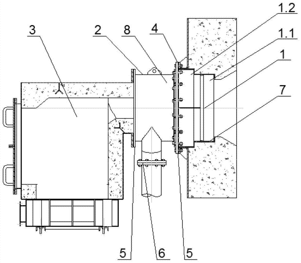
[0033] See Figure 2 to Figure 5 , The present invention discloses a regenerative burner for a heating furnace. The burner includes: a burner brick part 1, an air inlet unit 2, a heat storage box 3, a burner brick part 1 and a furnace wall Between the first flange 4, the second flange 5 arranged on both sides of the air inlet unit 2, and the third flange 6 arranged between the air inlet unit 2 and the air pipe; the air inlet unit 2 is arranged on the burner Between the mouth brick part 1, the heat storage tank 3.

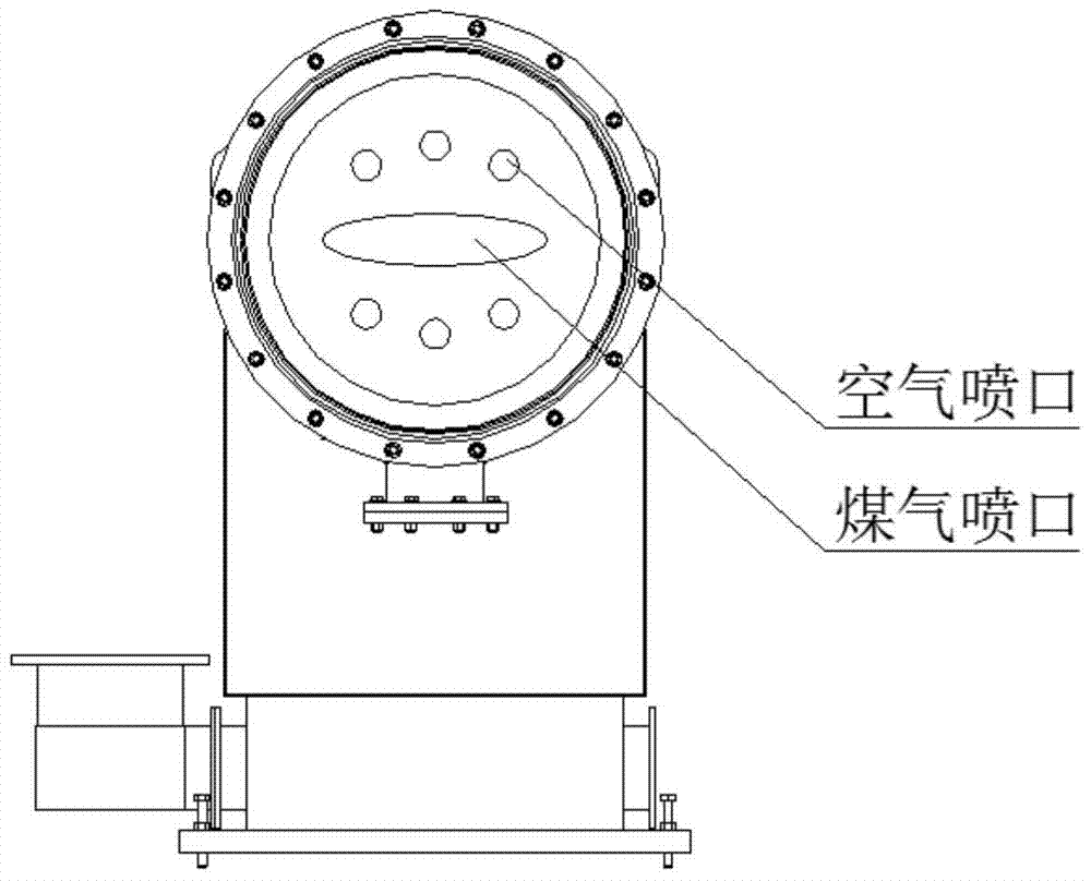
[0034] The burner brick part 1 includes a burner brick 1.1 made of high temperature and erosion resistant mullite castable material and a metal shell part 1.2; the two parts are poured together during production, and the air and gas channels are combined in On an independent burner brick, the structure is the same as a conventional burner. The inner ring is a gas nozzle and the outer ring is an air nozzle, which effectively organizes the combustion.

[0035] The instal...

Embodiment 2

[0040] The difference between this embodiment and the first embodiment is that in this embodiment, the heat storage box is provided with a honeycomb body and a block brick. The honeycomb body is all made of mullite material, which has a large specific surface area, and has a heat storage and heat release rate. Fast, low resistance loss, high temperature efficiency, can preheat the gas to 1000 ℃, maximize the recovery of waste heat. The retaining brick adopts high-alumina brick, which has the characteristics of high temperature resistance, which can effectively resist high-temperature heat radiation from the furnace and protect the honeycomb body.

[0041] A three-way reversing valve is installed on the flue gas and gas pipes in front of the burner, which is used to switch the gas and flue gas during combustion and heat storage. The flue gas branch pipe in front of each burner is equipped with a thermal resistance. When measuring the temperature When the set value is exceeded, the...


PUM


Abstract

The invention discloses a regenerative burner for a heating furnace, comprising a burner brick part, an air inlet unit, a heat storage box, a first flange arranged between the burner brick part and the furnace wall, and a The second flanges on both sides of the air inlet unit are arranged on the third flange between the air inlet unit and the air duct; the air inlet unit is arranged between the burner brick part and the heat storage tank; the burner brick part includes Burner brick and metal shell part made of high temperature and erosion-resistant mullite castable; the two parts are cast together during production, and the air and gas passages are combined on a separate burner brick with the same structure. Like conventional burners, the inner ring is a gas nozzle and the outer ring is an air nozzle, which effectively organizes combustion. The regenerative burner of the invention has high combustion efficiency, can be replaced, and has good temperature uniformity, solves many disadvantages of the traditional regenerative burner, improves product quality, reduces enterprise costs, and improves working conditions of workers.

Description

Technical field [0001] The invention belongs to the technical field of heating equipment, and relates to a heating furnace, in particular to a regenerative burner for the heating furnace. Background technique [0002] Blast furnace gas is a by-product produced in the ironmaking process of steel plants. The content of combustible components in blast furnace gas is only -30%. It has a low calorific value. When used directly, it cannot reach the temperature required for heating billets. It can only be combined with some high-calorific value gas such as coke. The mixed use of furnace gas has low utilization rate. In iron and steel enterprises, a large amount of blast furnace gas is discharged into the atmosphere by direct ignition, which not only wastes a lot of energy, but also seriously pollutes the environment. [0003] In the 1980s, regenerative combustion technology began to appear, which can store blast furnace gas to 1000°C, thereby achieving the purpose of using blast furnace g...

Claims


Application Information

Patent Timeline
Patent Type & Authority Patents(China)
IPC IPC(8): C21B5/06
Inventor 林建苏朱宏祥张晓桂杜鹏张永佳冯波吴振宇黄胜利都晓溪潘云
Owner FIVES STEIN METALLURGICAL TECH SHANGHAI CO LTD
Why Eureka
Try Eureka