
Impact resisting check valve

A check valve, anti-shock technology, applied in the direction of control valve, valve device, functional valve type, etc., can solve the problems of short service life of the check valve, damage to the sealing surface, valve leakage, etc., to avoid frequent repairs or maintenance, The effect of prolonging the service life and saving cost

Active Publication Date: 2015-10-28
NEWAY OIL EQUIP SUZHOU
View PDF9 Cites 1 Cited by
  • Summary
  • Abstract
  • Description
  • Claims
  • Application Information

AI Technical Summary

Problems solved by technology

[0004] The traditional horizontal check valve has a large impact force every time the disc is closed, which leads to frequent impacts on the sealing surface (usually the conical surface) of the lower part of the disc, resulting in damage and leakage of the valve
For example, in a check valve disclosed in Chinese utility model patent CN204284543U, although a valve stem is provided to limit the position of the valve disc, a large impact is still generated under the action of the spring when the valve disc is closed, and the sealing surface of the valve disc Appropriate protection measures are not taken, and the sealing surface is easily damaged. The service life of this check valve is generally not long, and the site replacement and maintenance are frequent

Method used


Image

  • Impact resisting check valve
  • Impact resisting check valve
  • Impact resisting check valve

Examples


Embodiment Construction

[0030] Preferred embodiments of the present invention will be described in detail below in conjunction with the accompanying drawings.

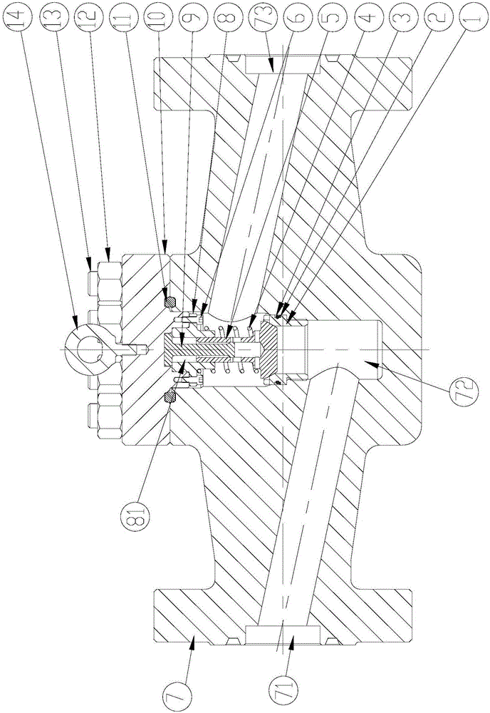
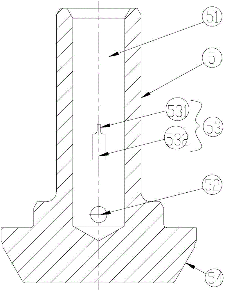
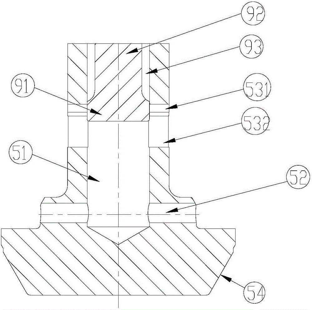
[0031] see Figures 1 to 5 , an anti-shock check valve, including a valve body 7, a valve seat 1, a valve disc 5, an elastic member 4 and a valve cover 10.

[0032] The valve body 7 has a liquid inlet passage 71 , a middle chamber 72 and a liquid outlet passage 73 connected thereto. The valve seat 1 is screwed into the middle chamber 72 and sealed by the retaining ring 2 and the O-ring.

[0033] The valve disc 5 is set on the valve seat 1 to move up and down, and the valve disc 5 cooperates with the valve seat 1 to open and close the middle cavity, and the elastic member 4 is set on the valve disc 5 so that the valve disc 5 has a tendency to close to the valve seat 1 . In this embodiment, the elastic member 4 is a spring.

[0034] The valve cover 10 is fixed on the valve body 7 through nuts 12 and studs 13 , and the valve cover 10 is close...


PUM


Abstract

The invention provides an impact resisting check valve. The impact resisting check valve is composed of a valve body, a valve seat, a valve clack, an elastic piece and a valve cover. The valve clack is arranged on the valve seat in a vertical moving mode. The elastic piece is arranged on the valve clack in a sleeving mode to make the valve clack have the tendency of being closed to the valve seat. A guide sleeve and a fixing plug are fixedly arranged above a middle cavity of the valve body. The fixing plug is located in the middle of the guide sleeve and extends downwards. The upper portion of the valve clack is arranged in the guide sleeve in a vertical sliding fit mode. A receding space is arranged above the valve clack and located on the guide sleeve. A piston hole for the fixing plug to be inserted therein is formed in the valve clack. A through hole communicated with the middle cavity is formed in the bottom of the side wall of the piston hole. A buffering structure hole communicated with the piston hole and the middle cavity is formed above the through hole. The buffering structure hole vertically extends in the length direction of the buffering structure hole. The buffering structure hole is provided with an upper section and a lower section which are communicated. The moving speed of the valve clack is controlled through the relative position relation of the fixing plug and the buffering structure hole. Impact force produced between the valve clack and the valve seat when the valve clack is closed is prevented, and therefore the service life of the valve is prolonged.

Description

technical field [0001] The invention relates to a lifting check valve used for oil exploitation pipelines, in particular to an anti-shock check valve which can prevent the sealing surface from being damaged due to multiple impacts of the valve clack. Background technique [0002] Check valve refers to the valve that relies on the flow of the medium itself to automatically open and close the disc to prevent the backflow of the medium, also known as check valve, one-way valve, reverse flow valve, and back pressure valve. The check valve is a kind of automatic valve, its main function is to prevent the reverse flow of the medium, the reverse rotation of the pump and the drive motor, and the discharge of the container medium. According to the structure, the check valve can be divided into three types: lift check valve, swing check valve and butterfly check valve. Lift check valve can be divided into two types: vertical and horizontal. [0003] The check valve used in oil explo...

Claims


Application Information

Patent Timeline
IPC IPC(8): F16K15/06
CPCF16K15/063
Inventor 卜步建王银利
Owner NEWAY OIL EQUIP SUZHOU
Learn More