Supercharge Your Innovation With Domain-Expert AI Agents!
A fuel-fixed cruising device for an automatic transmission car
What is Al technical title?
Al technical title is built by PatSnap Al team. It summarizes the technical point description of the patent document.
It is a technology of automatic transmission and automobile, which is applied in the direction of foot-operated starting device, arrangement of power device control mechanism, control device, etc. It can solve the problems of unstable speed control, fuel waste, and high price, and achieve the purpose of alleviating long-distance driving fatigue and increasing Driving pleasure, flexible and convenient operation
Inactive Publication Date: 2019-01-18
王洪利
View PDF7 Cites 0 Cited by
Summary
Abstract
Description
Claims
Application Information
AI Technical Summary
This helps you quickly interpret patents by identifying the three key elements:
Problems solved by technology
Method used
Benefits of technology
Problems solved by technology
[0002] At present, automobiles generally use a pedal-type accelerator control device. Because the driver's right foot is always in working condition in this control method, the driver's right leg will be fatigued, causing general discomfort and causing unstable speed control. The throttle will produce unstable oil supply, which will cause fuel waste when driving at a constant speed
In addition, some high-priced cars have begun to be equipped with cruise control systems, but they are expensive. Therefore, it is a technical problem that needs to be solved at present to design a cruise control device with constant fuel consumption, low cost, and easy installation.
Method used
Image
Click on the blue label to locate the original text in one second.
Reading with bidirectional positioning of images and text.
Examples
Embodiment Construction
[0013] The specific implementation of the present invention is given below in conjunction with the accompanying drawings.
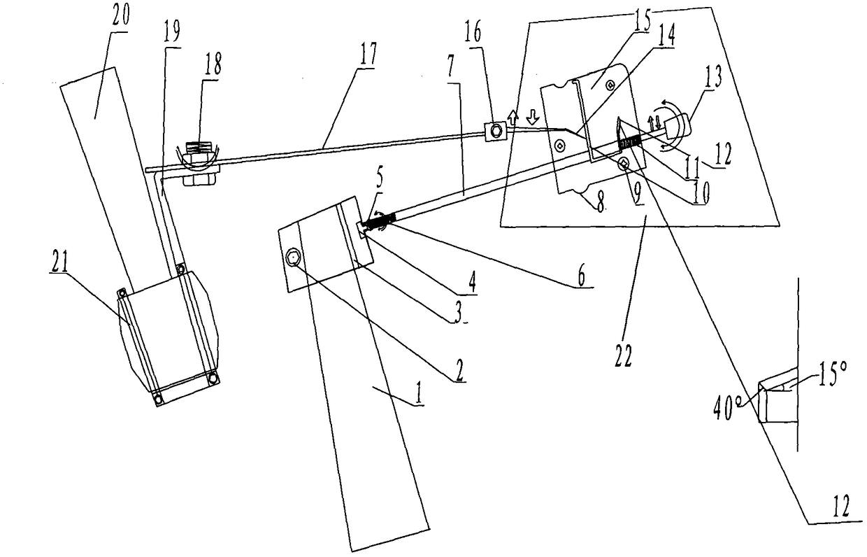
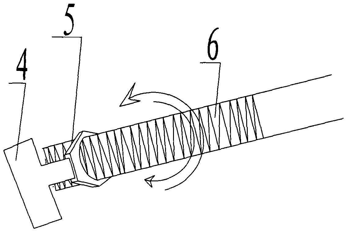
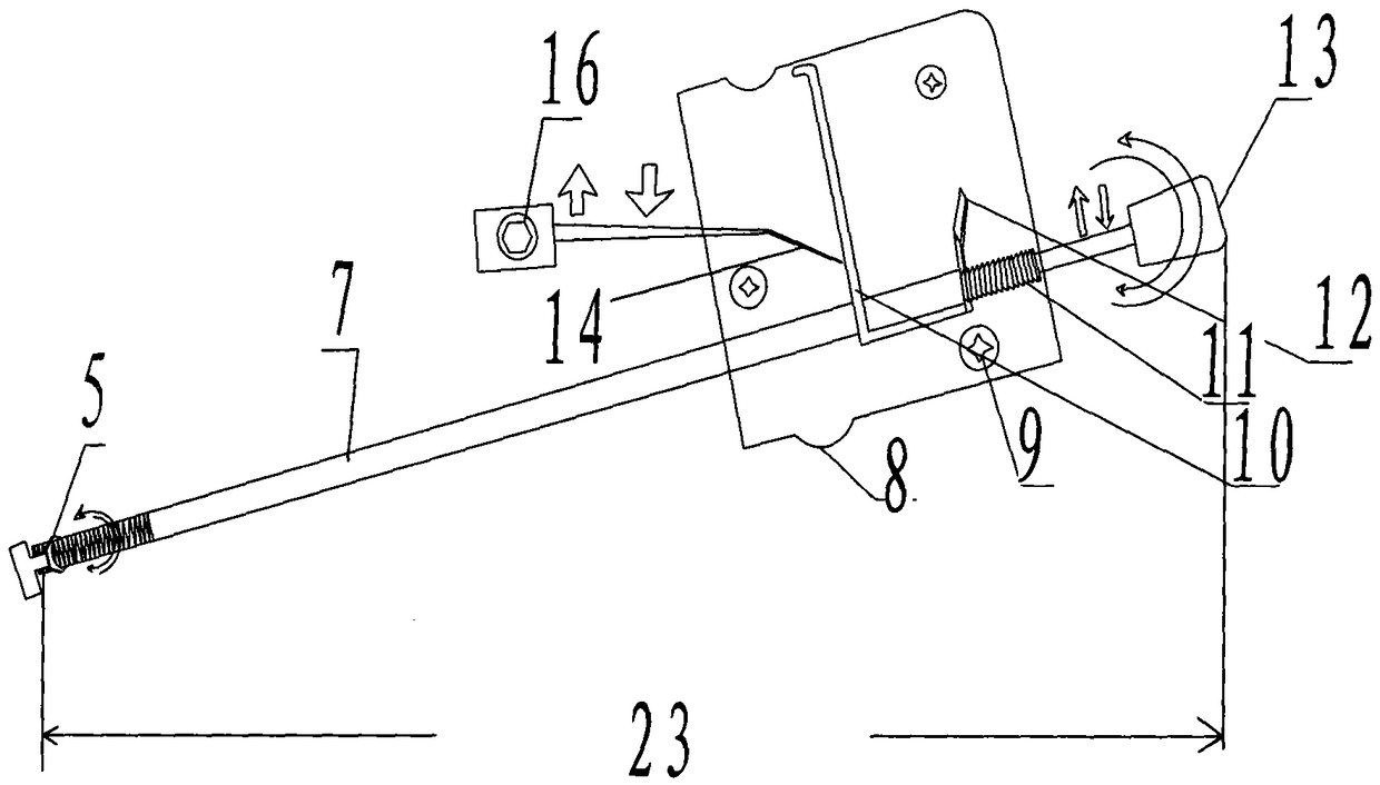
[0014] As shown in the figure, the present invention includes a refueling pedal fastening sleeve 2, a fastening sleeve partition 3, a T-shaped movable bolt 4, a nut 5, an oil fixing fine-tuning screw 6, an oil fixing rod connecting rod 7, an arc plate 8, Oil fixing rod barrier 10, tower type oil fixing screw rod 11, inclined oil fixing extinguisher 12, oil fixing rod handle 13, brake oil cut-off hook rod 14, fixed plate 15, oil cut-off hook rod adjustment bolt 16, brake breaker Composed of oil connecting rod 17, brake oil cut-off connecting rod fastening bolt 18, brake oil cut-off fastening sleeve connecting rod 19, brake pedal fastening sleeve 21, and oil fixing rod 23, it is characterized in that: refueling pedal fastening sleeve 2 is fixed on the refueling pedal 1, and the T-shaped movable bolt 4 is fixed on the fastening sleeve 2 of the fueling pedal....
PUM
Abstract
The invention discloses a constant oil cruise device of an automatic transmission vehicle. The constant oil cruise device can realize the constant oil cruise, is convenient to mount, and comprises an oil feeding pedal fastening sleeve, a fastening sleeve separating plate, a T-shaped movable plug, a nut, a constant oil fine adjustment screw rod, a constant oil rod connecting rod, an arc-shaped plate, a constant oil rod blocking fence, a tower type constant oil screw rod, a bevel constant oil pin, a constant oil rod handle, a braking and oil cutting drawing rod, a fixing plate, an oil cutting drawing rod adjusting bolt, a braking and oil cutting connecting rod, a braking and oil cutting connecting rod fastening bolt, a braking and oil cutting fastening sleeve connecting rod, a braking pedal fastening sleeve and a constant oil rod. When a vehicle travels at the speed of 50 kilometers per hour normally according to the road conditions or the speed limiting, the stress state of a pedal accelerator is unchanged, a constant oil rod is manually placed on the bevel constant oil pin, and the tower type constant oil screw rod is clamped with the bevel constant oil pin through the elastic effect of an oil feeding pedal, so that the oil consumption is fixed to be high than an immediate standard of oil consumption per hundred kilometers; the pedal accelerator is released at the moment, and the vehicle enters a constant oil cruise traveling state; the constant oil cruise traveling state can be canceled through gently treading a breaking pedal, gently treading the oil feeding pedal and manually moving the constant oil rod to left.
Description
technical field [0001] The invention relates to a fuel-fixed cruising device for an automatic transmission automobile, belonging to the technical field of automobile constant-speed cruising. Background technique [0002] At present, automobiles generally use a pedal-type accelerator control device. Because the driver's right foot is always in working condition in this control method, the driver's right leg will be fatigued, causing general discomfort and causing unstable speed control. The throttle will produce unstable oil supply, which will cause fuel waste when driving at a constant speed. In addition, some high-priced cars have begun to be equipped with cruise control systems, but they are expensive. Therefore, it is a technical problem to be solved at present to design a cruise control device with constant fuel consumption, low cost, and easy installation. Contents of the invention [0003] The technical problem to be solved by the present invention is a fuel-fixed c...
Claims
Application Information
Patent Timeline
Application Date:The date an application was filed.
Publication Date:The date a patent or application was officially published.
First Publication Date:The earliest publication date of a patent with the same application number.
Issue Date:Publication date of the patent grant document.
PCT Entry Date:The Entry date of PCT National Phase.
Estimated Expiry Date:The statutory expiry date of a patent right according to the Patent Law, and it is the longest term of protection that the patent right can achieve without the termination of the patent right due to other reasons(Term extension factor has been taken into account ).
Invalid Date:Actual expiry date is based on effective date or publication date of legal transaction data of invalid patent.
