Lock for a motor vehicle

A technology for motor vehicles and rotating locking forks, which is applied to locks in accident situations, fastening devices for wing sashes, fastening devices for buildings, etc., and can solve problems such as unlocking of locking devices and actuation of handles.

Active Publication Date: 2015-11-04
KIEKERT AG
View PDF6 Cites 4 Cited by
  • Summary
  • Abstract
  • Description
  • Claims
  • Application Information

AI Technical Summary

Problems solved by technology

[0008] In the event of a crash, the handle is accidentally actuated, which could result in the locking device being opened

Method used


Image

  • Lock for a motor vehicle
  • Lock for a motor vehicle
  • Lock for a motor vehicle

Examples


Embodiment Construction

[0054] It is pointed out that the proposed lock can be used in all conceivable locking devices. In a particularly preferred embodiment, the proposed lock can of course be used in a motor vehicle.

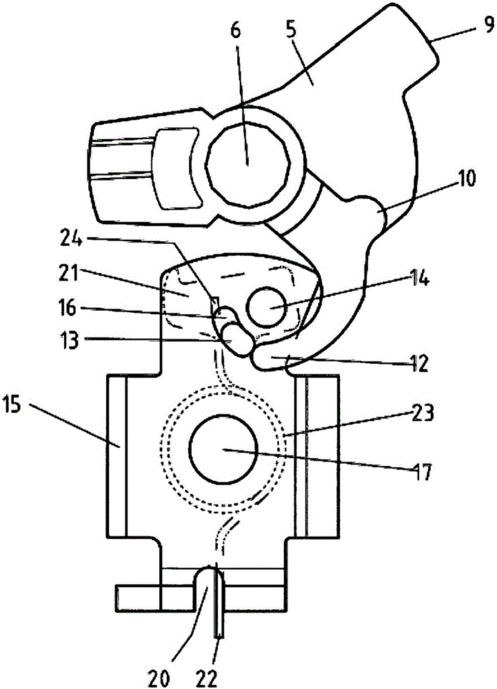
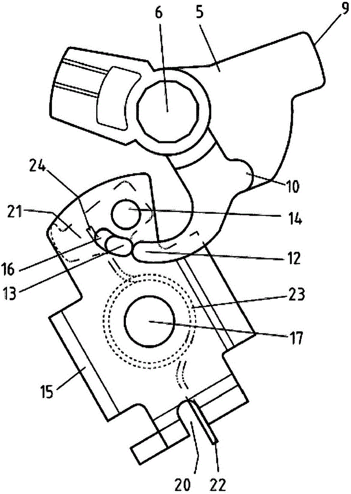
[0055] Below, the basic working method of the lock and the proposed locking mechanism are firstly described, such as Figure 1 to Figure 4 shown.

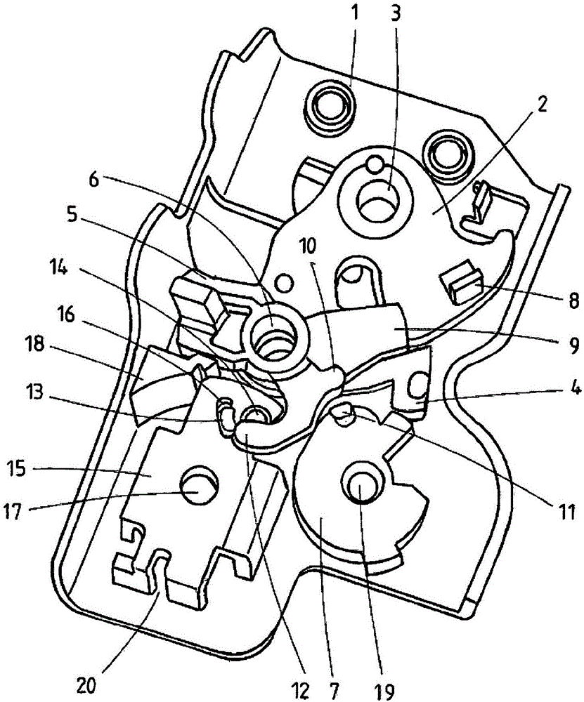
[0056] figure 1 Shown is a lock box 1 of a lock, in particular made of metal, which serves to support the locking device. The locking device comprises a rotatably mounted rotary latch 2 , preferably mainly made of metal, which is rotatable about its axis 3 . The locking device also comprises a main locking pawl 4, preferably mainly made of metal, and a pre-locking pawl 5, preferably mainly made of metal.

[0057] The main locking pawl 4 and the pre-locking pawl 5 are placed on top of each other and have a common rotation axis 6, so that the two locking pawls 4 and 5 can rotate independently of each other. Locking device also compris...


PUM


Abstract

The invention relates to a lock, in particular for a door or opening element of a motor vehicle. In order to avoid the unplanned opening of the lock in the event of a crash, the invention proposes a lock with a locking mechanism comprising a rotary latch (2), a pawl (4) for locking the rotary latch in a detent position, preferably a blocking lever (7) for blocking the pawl in the detent position and a release lever (5) for opening the locking mechanism, in particular by lifting the blocking lever out of the blocking position. The lock is provided with a rotation-lock device, by means of which an opening process of the locking mechanism caused by momentum or an impact can be prevented or blocked.

Description

technical field [0001] The invention relates to a lock for a motor vehicle according to the preamble of claim 1 . Background technique [0002] A lock for a motor vehicle comprises a locking device with a rotatably mounted rotary fork for receiving a stop, which is also referred to as a lock holder. The locking device also has a locking pawl, by means of which the rotary locking fork can be locked for holding the stop. [0003] The rotary yoke of a motor vehicle lock usually has a fork-shaped entry slot (also called an entry port) formed by the load arm and the capture arm. When the door or hatch is closed, the door or hatch - such as the hood or luggage compartment lid—the stop goes into the access slot. The stop or lock retainer then rotates the rotary fork from the open position towards the closed position until the locking pawl locks the rotary fork. This position is called the locked position. The stop cannot then leave the entry slot of the rotary yoke. [0004] F...

Claims


Application Information

Patent Timeline
Patent Type & Authority Applications(China)
IPC IPC(8): E05B77/06
CPCE05B77/06E05B77/04E05C3/12E05C19/02
Inventor H·瓦曼C·富克斯D·艾谢尔
Owner KIEKERT AG
Why Eureka
Try Eureka