Test body for determining rotation errors of a rotating apparatus

A technology of rotation device and rotation error, applied in the direction of using optical devices, measuring devices, instruments, etc., can solve problems such as cost

Active Publication Date: 2015-11-04
CARL ZEISS IND MESSTECHN GMBH
View PDF8 Cites 19 Cited by
  • Summary
  • Abstract
  • Description
  • Claims
  • Application Information

AI Technical Summary

Problems solved by technology

Depending on the number of rotating devices to be measured and monitored, considerable costs can be incurred here

Method used


Image

  • Test body for determining rotation errors of a rotating apparatus
  • Test body for determining rotation errors of a rotating apparatus
  • Test body for determining rotation errors of a rotating apparatus

Examples


Embodiment Construction

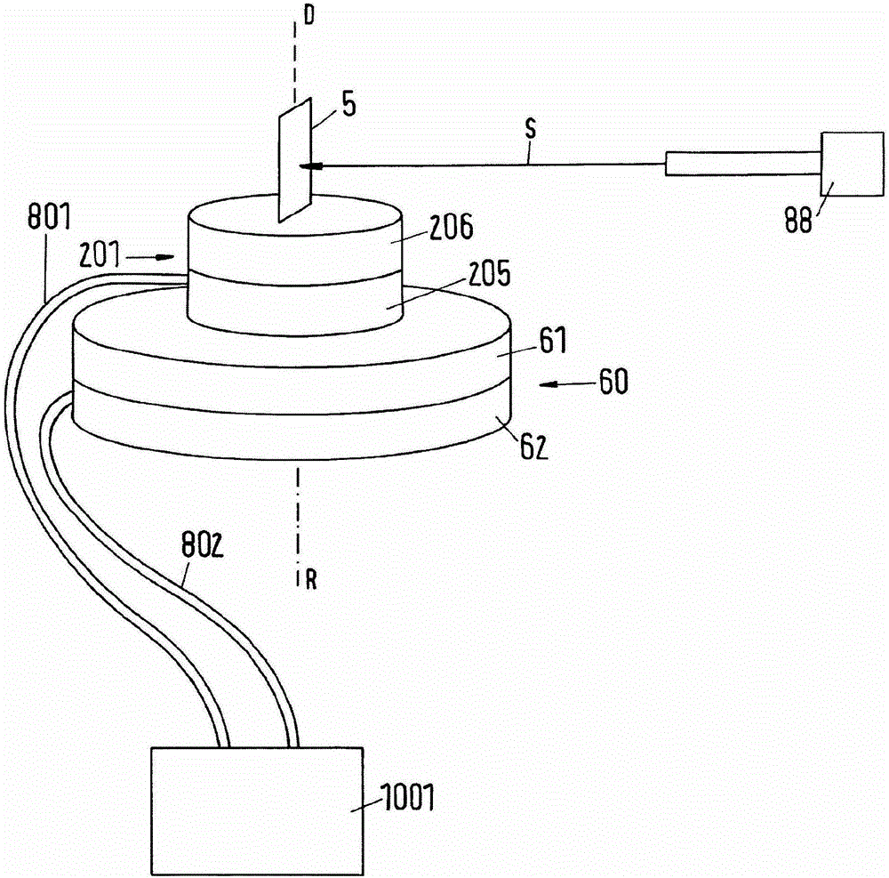
[0467] exist figure 1 A possible configuration for the error detection process is shown in : a rotary device 201 is mounted on a reference rotary device 60 , here a rotary table with a lower part 62 and a rotary disk 61 . The rotary device 201 is in this example also a rotary table in which a rotary angle measurement system (not shown) is to determine a rotary angle error. The turntable 201 has a lower part 205 and a turntable 206 . The lower part 205 of the rotary table 201 rests on the rotary disk 61 of the reference rotary device 60 . Due to the friction between the disk 61 and the lower member 205 and the own weight of the rotating disk 201 , the lower member 205 is connected to the rotating disk 61 without relative rotation. The disc 61 of the reference turntable 60 is rotatable relative to the lower part 62 about the axis R of the reference turntable. The disc 206 of the turntable 201 is rotatable about the axis D relative to the lower part 205 . Axes D and R are ar...


PUM


Abstract

Test body (1; 100; 101; 102; 103; 104; 105) for determining one or more rotation errors of a rotating apparatus (2; 201), in particular a rotating apparatus for a coordinate measuring machine, with respect to one or more degrees of freedom of movement, in which a real rotating movement of the rotating apparatus (2; 201) differs from an ideal rotating movement, wherein the test body comprises: a holder (3, 300) which, together with a part of the rotating apparatus (2, 201), can be rotated about an axis of rotation (D; A; B) and which is configured to arrange or fasten the test body with respect to the axis of rotation about which the test body can be rotated for the purpose of determining the rotation error(s), and a plurality of test elements (5, 8, 9; 5, 10; 500, 501, 800; 500, 502, 800; 800, 900, 1000; 503) which are rigidly connected to the holder or are formed on the holder, wherein each of the test elements is used to determine the rotation error with respect to one or more of the degrees of freedom of movement.

Description

technical field [0001] The invention relates to a test body for ascertaining a rotation error of a rotation device, in particular for a coordinate measuring machine, an assembly and a method for ascertaining such a rotation error. Background technique [0002] Rotary devices, such as rotary swivel joints or swivel tables for coordinate measuring machines, generally have an angle encoder, by means of which the current angular position of the rotary axis of the rotary device can be detected. In conventional incremental measuring systems this is mostly done with reference to reference markings. However, common angle measurement systems have errors which lead to measurement errors in coordinate measurement technology. [0003] In addition to errors caused by the angle measuring system itself, errors are additionally caused by the mechanism of the rotary device, in particular by the mounting / guiding of parts of the rotary device that can rotate about the axis of rotation, and by...

Claims


Application Information

Patent Timeline
Patent Type & Authority Applications(China)
IPC IPC(8): G01B21/04G01B5/24
CPCG01B21/042G01B5/24G01B21/22G01B11/26
Inventor D·塞茨T·黑尔德R·萨格米勒C-P·瓦尔尼
Owner CARL ZEISS IND MESSTECHN GMBH
Why Eureka
Try Eureka