Ladle filler sand discharge device and continuous casting ladle casting starting method

Active Publication Date: 2015-11-11
SHOUGANG JINGTANG IRON & STEEL CO LTD
View PDF9 Cites 9 Cited by
  • Summary
  • Abstract
  • Description
  • Claims
  • Application Information

AI Technical Summary

Problems solved by technology

[0004] The drainage sand discharge device and the continuous casting ladle opening method provided by the application solve or partially solve the technical problems in the prior art that the drainage sand enters the tundish to affect the quality of the casting slab, the quality of the drainage sand is poor, and the technical problems of reducing the self-opening rate of the ladle , to avoid drainage sand from entering the tundish, improve the quality of molten steel in the tundish, ensure the quality of casting slab, improve the self-opening rate of ladle, reduce the probability of forced bare pouring of ladle, and ensure the technical effect of molten steel quality

Method used


Image

  • Ladle filler sand discharge device and continuous casting ladle casting starting method
  • Ladle filler sand discharge device and continuous casting ladle casting starting method
  • Ladle filler sand discharge device and continuous casting ladle casting starting method

Examples


Embodiment 1

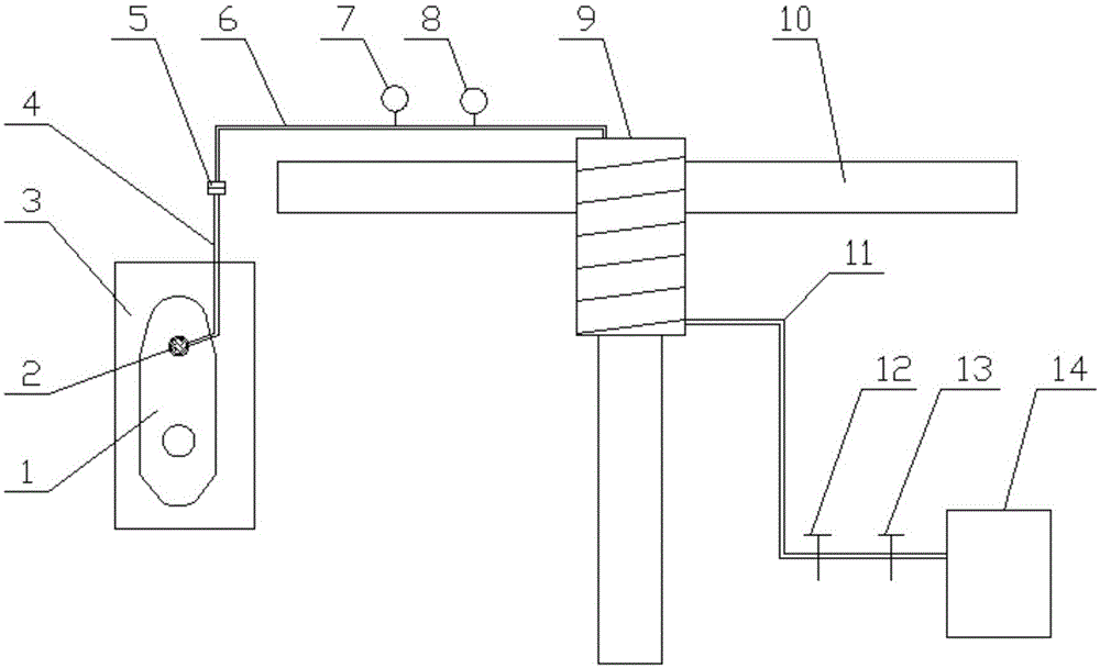
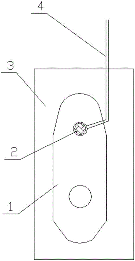
[0063] Fix the ladle on the fork wall seat of the ladle turret 10 above the accident ladle, and the oil cylinder of the ladle drives the movable frame 3, so that the upper nozzle of the ladle mechanism is connected with the lower nozzle, and the drainage sand in the ladle is exhausted. When the ladle mechanism flows out When the molten steel forms a circular flow, immediately slide the movable frame 3 so that the vent plug 2 on the slide plate 1 is located at the position of the upper nozzle of the ladle mechanism, connect the second argon pipe 6 and the third argon pipe 4 through the quick joint 5, and open the pressure regulating valve 13 and The flow regulating valve 12, the argon gas supply part 14 continuously feed argon gas into the upper nozzle through the argon gas pipeline and the vent plug 2, control the pressure of the argon gas at 0.8Mpa through the pressure detection part 8, and control the flow rate of the argon gas through the flow detection part 7 At 150L / min, t...

Embodiment 2

[0065] Fix the ladle on the fork wall seat of the ladle turret 10 above the accident ladle, and the oil cylinder of the ladle drives the movable frame 3, so that the upper nozzle of the ladle mechanism is connected with the lower nozzle, and the drainage sand in the ladle is exhausted. When the ladle mechanism flows out When the molten steel forms a circular flow, immediately slide the movable frame 3 so that the vent plug 2 on the slide plate 1 is located at the position of the upper nozzle of the ladle mechanism, connect the second argon pipe 6 and the third argon pipe 4 through the quick joint 5, and open the pressure regulating valve 13 and The flow regulating valve 12, the argon gas supply part 14 continuously feed argon gas into the upper nozzle through the argon gas pipeline and the vent plug 2, control the pressure of the argon gas at 1.2Mpa through the pressure detection part 8, and control the flow rate of the argon gas through the flow detection part 7 At 300L / min, t...

Embodiment 3

[0067] Fix the ladle on the fork wall seat of the ladle turret 10 above the accident ladle, and the oil cylinder of the ladle drives the movable frame 3, so that the upper nozzle of the ladle mechanism is connected with the lower nozzle, and the drainage sand in the ladle is exhausted. When the ladle mechanism flows out When the molten steel forms a circular flow, immediately slide the movable frame 3 so that the vent plug 2 on the slide plate 1 is located at the position of the upper nozzle of the ladle mechanism, connect the second argon pipe 6 and the third argon pipe 4 through the quick joint 5, and open the pressure regulating valve 13 and The flow regulating valve 12, the argon gas supply part 14 continuously feed argon gas into the upper nozzle through the argon gas pipeline and the vent plug 2, control the pressure of the argon gas at 1.5Mpa through the pressure detection part 8, and control the flow rate of the argon gas through the flow detection part 7 At 400L / min, t...


PUM


Abstract

The invention relates to a ladle filler sand discharge device and a continuous casting ladle casting starting method. The ladle filler sand discharge device comprises a sliding plate, a vent plug and an argon supply component. The sliding plate is fixed into a movable frame of a ladle mechanism and provided with a vent plug hole. The vent plug is fixed into the vent plug hole. The argon supply component is communicated with the vent plug through an argon pipeline. The continuous casting ladle casting starting method comprises the steps of completing ladle preparation work, discharging ladle filler sand in a ladle completely, blowing argon into an upper nozzle of the ladle and starting casting of the ladle. By the adoption of the ladle filler sand discharge device and the continuous casting ladle casting starting method, the ladle filler sand can be effectively prevented from entering into a tundish, the quality of casting blanks is guaranteed, the free opening rate of the ladle is improved, and forced naked casting probability of the ladle is lowered, and the quality of molten steel is guaranteed.

Description

technical field [0001] The invention relates to the technical field of steelmaking, in particular to a drainage sand discharge device and a continuous casting ladle opening method. Background technique [0002] With the continuous development of the iron and steel industry, the quality requirements of molten steel are getting higher and higher. At present, the ladle pouring method in the iron and steel industry is to use ladle drainage sand for drainage. In continuous casting production, in order to ensure the protective pouring of the ladle, the drainage sand drains the molten steel into the tundish. After this traditional method introduces the drainage sand into the tundish, the SiO in the drainage sand 2 、Cr 2 o 3 When it enters the tundish, it will affect the quality of the slab, and the drainage sand is easy to form a mixed solidified body of steel sand at the nozzle of the ladle, which reduces the self-opening rate of the ladle. If the ladle cannot be opened automat...

Claims


Application Information

Patent Timeline
Patent Type & Authority Applications(China)
IPC IPC(8): B22D41/44
Inventor 彭国仲李金柱张丙龙苏震霆卢家凯杨春宝白健肖华生单庆林杨晓山
Owner SHOUGANG JINGTANG IRON & STEEL CO LTD
Why Eureka
Try Eureka