Cutting mechanism

A technology of cutting knife and guide rail, applied in metal processing and other directions, can solve the problems of low work efficiency, terminal deformation, affecting the accuracy of cutting position, etc., and achieve the effect of accurate cutting position

Active Publication Date: 2015-11-11
SANHE IND AUTOMATION EQUIP CO LTD SHUNDE DISTRICT FOSHAN CITY
View PDF6 Cites 4 Cited by
  • Summary
  • Abstract
  • Description
  • Claims
  • Application Information

AI Technical Summary

Problems solved by technology

[0002] The traditional terminal cutting uses manual terminal material cutting tools, which has low work efficiency and the cutting quality cannot be guaranteed
At present, there are also some automatic cutting equipments on the market. The common problem of these automatic cutting equipments is that the material is prone to displacement during the cutting process, which affects the accuracy of the cutting position, and is prone to burrs, terminal deformation or material blocking.

Method used


Image

  • Cutting mechanism
  • Cutting mechanism
  • Cutting mechanism

Examples


no. 1 example

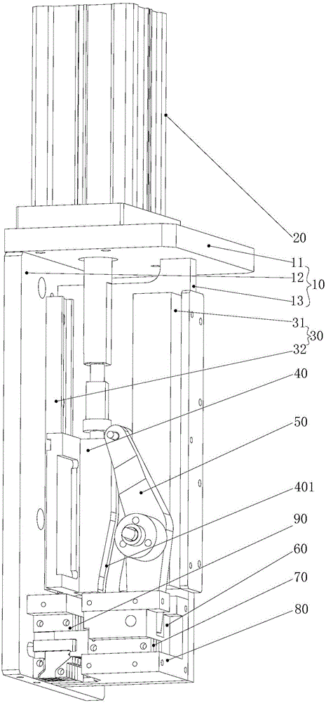
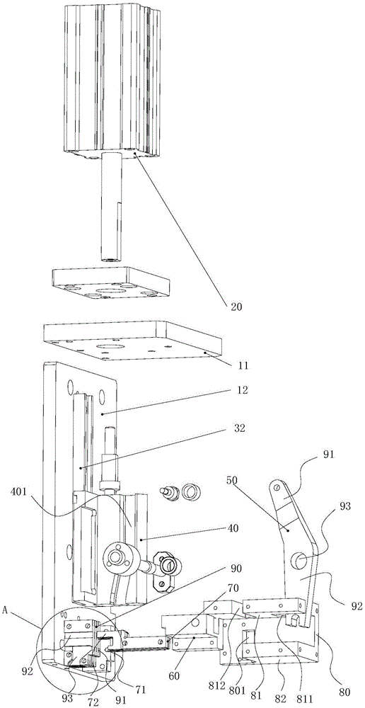
[0034] see Figure 1 ~ Figure 3 , the first embodiment is a preferred embodiment of the present invention, the material cutting mechanism includes a fixed seat 10, a cylinder 20, a guide rail 30, a guide slider 40, a swing rod 50 and a cutter slider 60, a cutter 70, a guide Support 80 and cutter backing plate 90. The fixed seat 10 specifically includes a horizontal plate 11 arranged in the horizontal direction, a vertical plate 12 arranged in the vertical direction, an intermediate vertical plate 13 perpendicular to the horizontal plate 11 and the vertical plate 12, and the vertical plate 12, the horizontal plate 11 and the intermediate vertical plate 13 are two by two. The three-dimensional fixed seats 10 are formed perpendicular to each other. The output shaft of the air cylinder 20 passes through the horizontal plate 11 and is connected with the guide slider 40 . The guide rail 30 includes a first guide rail 31 installed on the middle vertical plate 13 and a second guide ...

no. 2 example

[0041] refer to Figure 4 , The second embodiment is a further improvement of the material cutting mechanism in the first embodiment. This material cutting mechanism has the functions of cutting material and playing terminals at the same time. On the basis of the first embodiment, the material cutting mechanism further includes a knife bar connecting block 210 and a terminal knife 220. The guide slider 40 is composed of a fixedly connected terminal knife guide slider and a swing rod guide slider. The terminal knife guide slide The block is provided with a limit chute 402, the knife bar connecting block 210 is slidably connected with the guide slider 40, the afterbody of the terminal knife 220 is inserted in the knife bar connecting block 210, the head of the terminal knife 220 stretches into the guide bracket 90, and the terminal knife The moving direction of the terminal knife 220 is perpendicular to the moving direction of the cutter 70 , and the terminal knife 220 includes ...

no. 3 example

[0044] refer to Figure 5 and Figure 6 , this embodiment is a further optimization of the material cutting mechanism in the second embodiment. On the basis of the second embodiment, the material cutting mechanism provided in this embodiment also includes a terminal knife box 310, and the terminal knife box 310 is equipped with a cover plate 320, the terminal knife box 310 is set on the outer periphery of the terminal knife 220, the terminal knife 220 is accommodated in the terminal knife box 310, one end of the terminal knife box 310 is in contact with the knife bar connecting block 210, and the other end of the terminal knife box 310 is provided with a terminal Guide groove 311, feed port 312, and cutter hole 313, terminal guide groove and terminal knife are set in cooperation, cutter hole 313 is set in cooperation with cutter 70, and feed port is arranged on the side of terminal knife box, and guide bracket 80 The feeding port 801 is connected. When the terminal is punche...


PUM


Abstract

The invention discloses a cutting mechanism which is provided with a fixing seat, guide rails and a guiding slide block, wherein the fixing seat, the guide rails and the guiding slide block can guarantee the precision of a cutting action. A cylinder is used for driving the guiding slide block to slide along the guide rails. A curved guiding groove is formed in the guiding slide block. One end of a swing rod is connected with the guiding slide block in a sliding mode, and the other end of the swing rod is connected with a cutter slide block. The middle of the swing rod is connected with the first guide rail through an eccentric shaft and a needle bearing. The cutter slide block moves in a reciprocating mode in the slide block guiding groove to drive a cutter to cut materials continuously, and a cutter groove is matched with the cutter. According to the cutting mechanism, the automatic cutting process is achieved, and the cutting mechanism has the advantages that the cutting position is precise, and burrs are avoided. The cutting mechanism can be further improved to have terminal cutting and crimping functions.

Description

technical field [0001] The invention relates to the field of terminal processing, in particular to a terminal material cutting mechanism. Background technique [0002] Traditional terminal cutting uses manual terminal material cutting tools, which has low work efficiency and cannot guarantee the cutting quality. At present, there are also some automatic cutting equipments on the market. The common problem of these automatic cutting equipments is that the material is prone to displacement during the cutting process, which affects the accuracy of the cutting position, and is prone to burrs, terminal deformation or material blocking. Contents of the invention [0003] In order to overcome the above-mentioned shortcomings in the prior art, the object of the present invention is to provide a cutting mechanism with precise cutting position, no deformation and no burrs. [0004] In order to achieve the above object, the present invention adopts following technical scheme: [00...

Claims


Application Information

Patent Timeline
IPC IPC(8): B26D1/06B26D5/16
Inventor 刘晖张礼华
Owner SANHE IND AUTOMATION EQUIP CO LTD SHUNDE DISTRICT FOSHAN CITY
Why Eureka
Try Eureka