Multi-target Continuous Imaging Bias Angle Compensation Method

A compensation method and technology of drift angle, applied in the field of aerospace remote sensing imaging tasks

Active Publication Date: 2018-02-09
SHANGHAI SATELLITE ENG INST
View PDF3 Cites 0 Cited by
  • Summary
  • Abstract
  • Description
  • Claims
  • Application Information

AI Technical Summary

Problems solved by technology

[0004] The present invention aims at the TDICCD camera equipped with an oscillating mirror existing in the prior art when performing multi-target continuous imaging tasks, the camera realizes the expansion of the ground field of view through the oscillating mirror, and the continuous movement of the oscillating mirror causes the continuous change of the optical axis of the camera , the problem that the satellite cannot compensate the drift angle around the yaw axis in a conventional way, a multi-target continuous imaging drift angle compensation method is proposed. This method combines the needs of engineering applications with the WGS84 ground-fixed position velocity, The expected attitude angle, the swing angle of the pendulum mirror, etc. are used as the input quantities for the calculation of the drift angle, and the attitude control target attitude is calculated by the drift angle deviation quaternion, and the drift angle compensation method for rotating around the instantaneous virtual optical axis is given, which can be used without judging the swing mirror. In the case of swinging flags, continuously output the desired attitude angle

Method used


Image

  • Multi-target Continuous Imaging Bias Angle Compensation Method
  • Multi-target Continuous Imaging Bias Angle Compensation Method
  • Multi-target Continuous Imaging Bias Angle Compensation Method

Examples


Embodiment

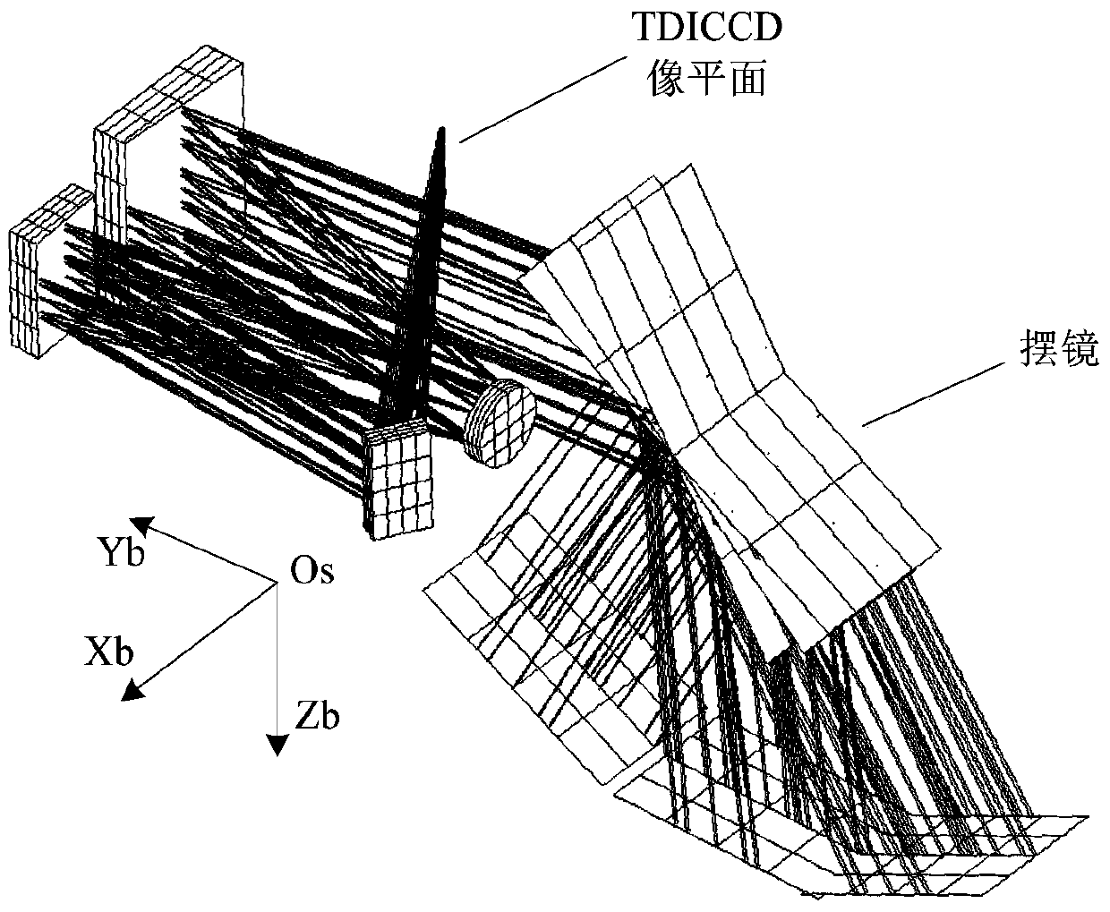
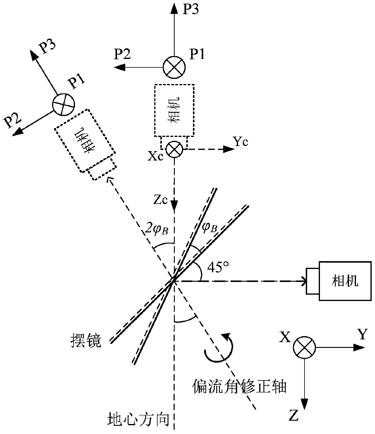
[0079] This embodiment provides a multi-target continuous imaging bias angle compensation method, which solves the problem that when a TDICCD camera equipped with a oscillating mirror performs a multi-target continuous imaging task, the camera realizes the expansion of the ground field of view through the oscillating mirror. The motion causes the continuous change of the optical axis of the camera, and the satellite cannot compensate the drift angle around the yaw axis in a conventional way.

[0080] In order to describe the technical content, structural features, achieved goals and beneficial effects of this embodiment in detail, this embodiment will be described in detail below in conjunction with the accompanying drawings.

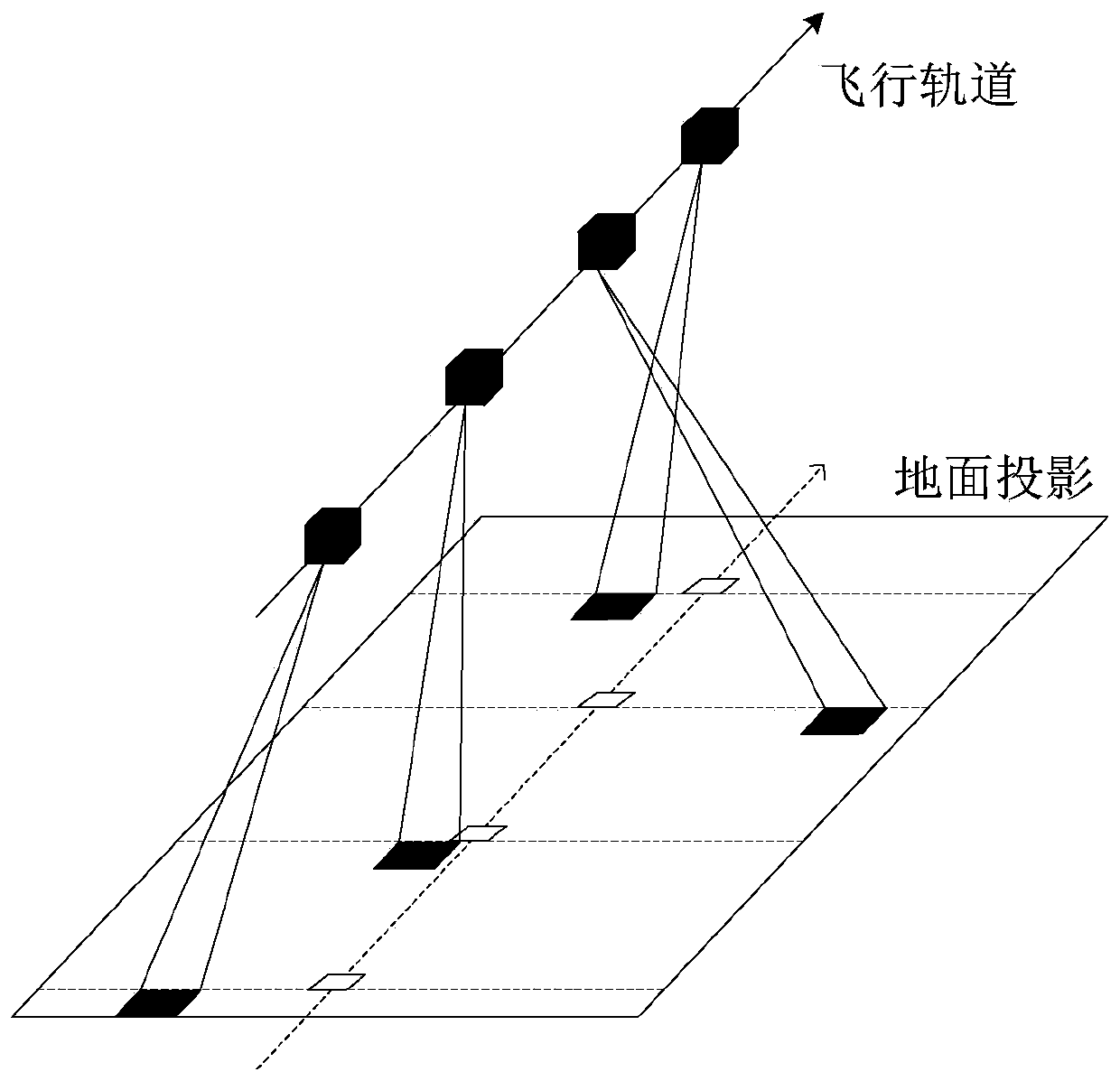
[0081] The same-orbit multi-target imaging is to complete the imaging of multiple targets that can be observed in the orbit during the single-track imaging process. The satellite is equipped with a TDICCD push-broom camera, which relies on the rolling ax...


PUM


Abstract

The invention provides a multi-target continuous imaging drift angle compensation method. The method comprises the steps that A, an equivalent light path of a camera with a swing mirror is built; B, an image moving speed and a drift angle are calculated; C, a drift angle deviation quaternion for attitude compensation is calculated. The problem that when the TDICCD camera with the swing mirror is used for executing a multi-target continuous imaging task, due to continuous movement of the swing mirror, a camera optical axis continuously changes, a satellite cannot carry out drift angle compensation around a yam axis in a conventional mode is solved. For meeting engineering application requirements, the WGS84 conventional terrestrial system position speed, expected attitude angle, swing mirror swing angle and the like are used as input for drift angle calculation, the drift angle deviation quaternion is used for resolving an attitude control target attitude, a drift angle compensation method rotating around an instantaneous virtual optical axis is given, and expected attitude angles can be continuously output on the condition of not judging a swing mirror swing target.

Description

technical field [0001] The invention relates to the technical field of aerospace remote sensing imaging tasks, in particular to a multi-target continuous imaging drift angle compensation method when the multi-target continuous imaging on the same orbit is carried out by means of an aerospace vehicle. Background technique [0002] The TDICCD camera uses time-delay integration as the receiver, and solves the problem of insufficient light flux of traditional area array cameras through multiple exposures. The camera optical system can use a small relative aperture reentrant or total reflection optical system, which directly reduces the volume of the optical load. . When the camera is working, it is necessary to ensure that the direction of the linear array push-broom is consistent with the direction of the target image movement speed, and to match the transfer speed of the photogenerated charge packet with the target image movement speed to ensure the imaging quality. When there...

Claims


Application Information

Patent Timeline
Patent Type & Authority Patents(China)
IPC IPC(8): G01C25/00
CPCG01C25/00
Inventor 崔本杰成飞陈锋范凯张健
Owner SHANGHAI SATELLITE ENG INST
Why Eureka
Try Eureka