Cooking apparatus

A technology for cooking devices and cooking chambers, which is applied to electric heating devices, household stoves/stoves, heating methods, etc., and can solve the problems of increasing the height and width restrictions of cooking chambers

Active Publication Date: 2009-08-19
LG ELECTRONICS INC
View PDF0 Cites 1 Cited by
  • Summary
  • Abstract
  • Description
  • Claims
  • Application Information

AI Technical Summary

Problems solved by technology

[0007] However, since the main parts, the operation panel, and the control panel are all installed on one side of the cooking cavity, conventional cooking devices have limitations in increasing the height and width of the cooking cavity.

Method used


Image

  • Cooking apparatus
  • Cooking apparatus
  • Cooking apparatus

Examples


Embodiment Construction

[0035] Hereinafter, the present invention will be described in detail with reference to the accompanying drawings.

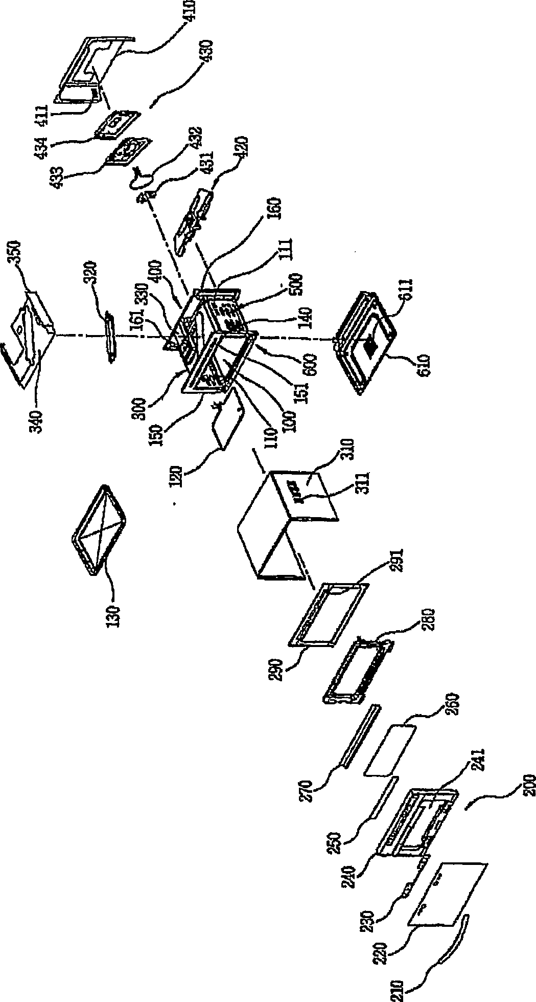
[0036] figure 1 It is an exploded schematic view of the main structure of the cooking device according to the present invention, which shows the cooking cavity 100, the door 200, the upper space 300 located above the cooking cavity 100, the rear space 400 located behind the cooking cavity 100, and the cooking cavity 100. The side space 500 on the side and the lower space 600 below the cooking cavity 100.

[0037] The cooking cavity 100 is a space for cooking food and is defined by the inner shell 110. The heater 120 is disposed at the upper part of the interior of the cooking cavity 100, and the plate or shelf 130 is disposed in the cooking cavity 100. The inner shell 110 includes an inlet (not shown) and an outlet 111 formed on the side to form an air flow path to remove heat and smell in the cooking cavity 100. An example of the heater 120 is a sheath heater. Re...


PUM


Abstract

In order to provide a cooking apparatus having an expanded cooking cavity with an increase in height and width and providing an expanded visual field for the cooking cavity, the present invention discloses a cooking apparatus, comprising: a cooking cavity; an upper space located over the cooking cavity; a door covering the cooking cavity and the upper space, opening the cooking cavity from the upper space side and provide with a door panel; an operating panel installed at an upper portion of the door to be positioned to the upper space, the operating panel being located in front of the door panel; and a control panel installed at an upper portion of the door to be positioned to the upper space, the control panel being located at the door panel and rear the operating panel and cooperating with the operating panel.

Description

Technical field [0001] The present invention generally relates to a cooking device, and more specifically, to a cooking device having an expanded cooking cavity with increased height and width and providing the cooking cavity with an expanded visual field. Background technique [0002] Korean Patent Application Publication No. 2005-0083504 discloses a typical example of a cooking device that has main components provided on one side of a cooking cavity, including a magnetron, a high voltage transformer, a high voltage capacitor, and a cooling fan. Korean Patent Application Publication No. 2006-0037003 discloses a cooking device which has main components installed on the upper side of a cooking cavity and houses a convection heater assembly on the rear wall of the cooking cavity. These main components include: Magnetrons, high-voltage transformers and high-voltage capacitors. Korean Utility Model Application Publication No. 1999-0010444 discloses a cooking device that has main comp...

Claims


Application Information

Patent Timeline
Patent Type & Authority Applications(China)
IPC IPC(8): F24C7/08
CPCF24C15/04F24C7/082F24C15/006F24C7/085F24C15/02H05B6/642
Inventor 金起荣金完洙
Owner LG ELECTRONICS INC
Why Eureka
Try Eureka