
Waveguide structure, display device, and electronic equipment

A technology of waveguide structure and waveguide layer, which is applied in light guides, optics, instruments, etc., can solve the problems of affecting display effect, entrance pupil image output, and display effect deterioration

Active Publication Date: 2019-12-20
SHENZHEN ORBBEC CO LTD
View PDF13 Cites 8 Cited by
  • Summary
  • Abstract
  • Description
  • Claims
  • Application Information

AI Technical Summary

Problems solved by technology

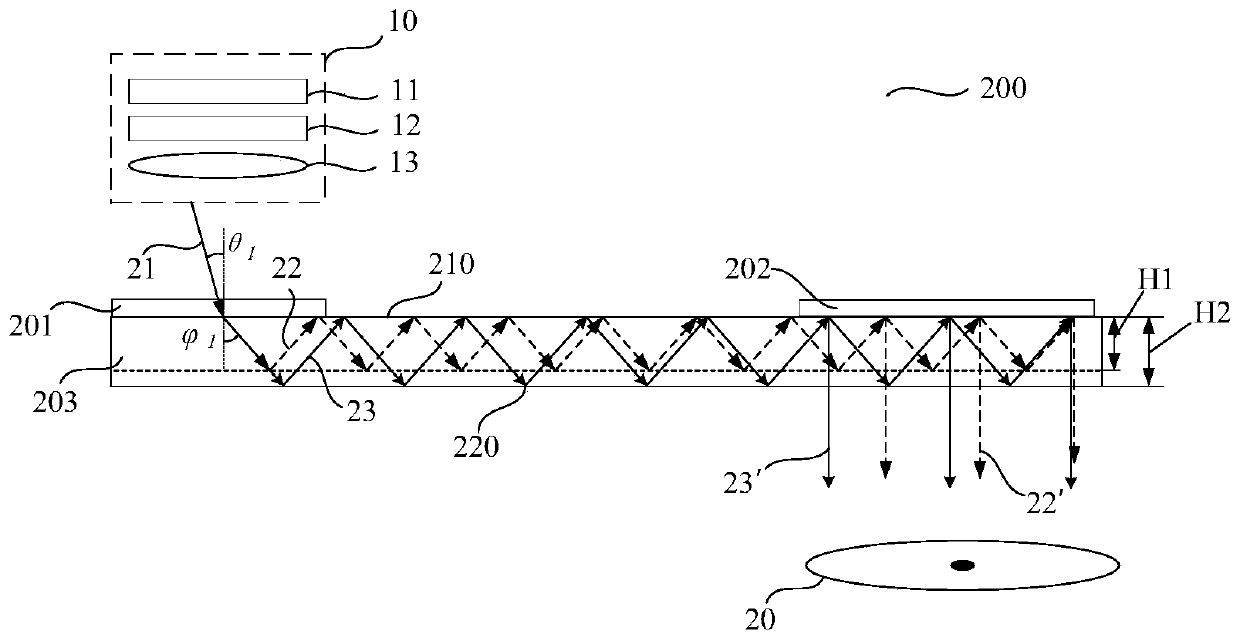
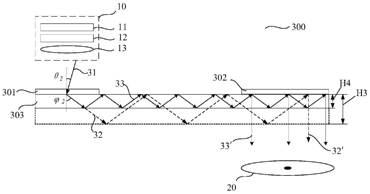
[0003] For the optical waveguide coupled by the grating, in addition to considering the change of the diffraction angle of the grating with the wavelength, it is also necessary to consider that the diffraction angle is affected by the field of view of the system. For beams of different fields of view, due to the difference in diffraction angle , the field of view of the exit pupil is also different, which will lead to the deterioration of the display effect of the waveguide, and the entrance pupil image cannot be clearly and completely output to the human eye, and because the in-coupling grating has a certain size, when part of the beam propagates in the waveguide, it will The phenomenon of re-coupling into the grating occurs, causing energy loss, and will also affect the display effect of the corresponding FOV

Method used


Image

  • Waveguide structure, display device, and electronic equipment
  • Waveguide structure, display device, and electronic equipment
  • Waveguide structure, display device, and electronic equipment

Examples


Embodiment Construction

[0021] In the following description, specific details such as specific system structures and technologies are presented for the purpose of illustration rather than limitation, so as to thoroughly understand the embodiments of the present application. It will be apparent, however, to one skilled in the art that the present application may be practiced in other embodiments without these specific details. In other instances, detailed descriptions of well-known systems, devices, circuits, and methods are omitted so as not to obscure the description of the present application with unnecessary detail.

[0022] It should be understood that when used in this specification and the appended claims, the term "comprising" indicates the presence of described features, integers, steps, operations, elements and / or components, but does not exclude one or more other Presence or addition of features, wholes, steps, operations, elements, components and / or collections thereof.

[0023] It should...


PUM


Abstract

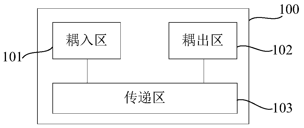
The application is suitable for the technical field of the optical device, and provides a waveguide structure, a display device, and electronic equipment. The waveguide structure comprises a coupling-in area, a coupling-out area and a transfer area; the transfer area comprises N waveguide layers, and N is positive integer greater than 1; the coupling-in area couples an incident beam into the transfer area, and the light coupled into the transfer area is divided into N parts according to a diffraction angle, and the beam with comparatively small diffraction angle is propagated in the waveguidelayer with comparatively large thickness. The exit pupil energy and the exit pupil range of the beam are improved.

Description

technical field [0001] The present application belongs to the technical field of optical devices, and in particular relates to a waveguide structure, a display device and electronic equipment. Background technique [0002] In the prior art, head-mounted display devices use planar optical waveguides as display devices, including grating optical waveguides or array optical waveguides. In order to realize the color imaging effect of the grating-type head-mounted display device, the existing technology adopts the multi-layer optical waveguide spectroscopic technology to transmit the light of RGB three colors respectively, and uses the critical condition of total reflection to filter the light of different wavelengths, so that the specific wavelength The light propagates in the designated waveguide layer. [0003] For the optical waveguide coupled by the grating, in addition to the change of the diffraction angle of the grating with the wavelength, it is also necessary to consid...

Claims


Application Information

Patent Timeline
IPC IPC(8): G02B6/00G02B27/01
CPCG02B6/0078G02B27/0172G02B2027/0123
Inventor 孙飞崔东曜周兴
Owner SHENZHEN ORBBEC CO LTD
Learn More