Aerial work platform with easy-to-operate platform structure

A technology of aerial work platform and platform structure, which is applied in the direction of lifting device, etc., can solve the problems of low operation efficiency, negative impact of tire walking passability, inconvenience, etc., and achieve the effect of fixing

Inactive Publication Date: 2015-11-18
ZHEJIANG DINGLI MACHINERY CO LTD
View PDF11 Cites 20 Cited by
  • Summary
  • Abstract
  • Description
  • Claims
  • Application Information

AI Technical Summary

Problems solved by technology

[0003] The existing structure of the aerial work platform usually installs support plates on both sides of the base to achieve the stability of high-altitude operations, which can play a supporting role in the process of tire height imbalance. It is a fixed installation structure, and the support plate will have a certain negative impact on the walking performance of the tire
[0004] In order to ensure the safety of the operators on the working platform, a railing door needs to be installed at the entrance of the working platform. The opening of the existing railing door lock is relatively complicated, which causes great inconvenience when the operator climbs the ladder to enter the working platform
[0005] In order to improve the activity space on the work platform, the work platform usually includes a platform fixed base plate and a sliding base plate that can slide relatively, and the relative fixation between the sliding base plate and the platform fixed base plate is realized through the movable platform lock. The existing movable platform lock operation Complicated, some even need to plug and unplug the fixed pin, so the operation efficiency is low

Method used


Image

  • Aerial work platform with easy-to-operate platform structure
  • Aerial work platform with easy-to-operate platform structure
  • Aerial work platform with easy-to-operate platform structure

Examples


Embodiment Construction

[0035] The present invention will be further described in detail below in conjunction with the accompanying drawings and examples. The following examples are explanations of the present invention and the present invention is not limited to the following examples.

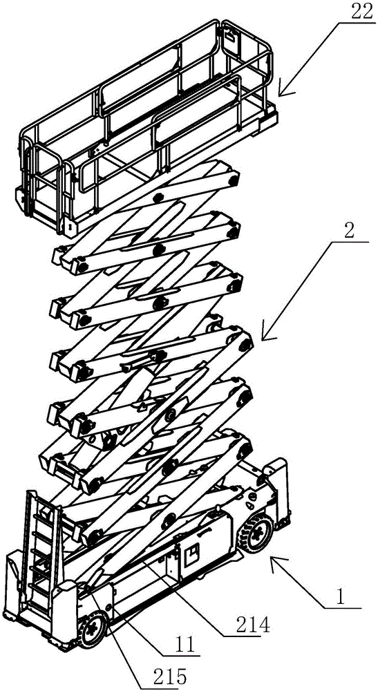
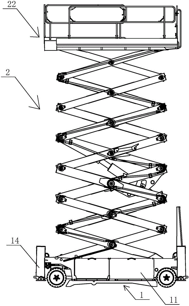
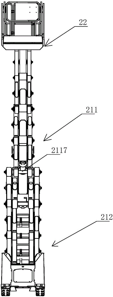
[0036] see Figure 1-Figure 22The scissor-type aerial work platform in this embodiment includes a traveling chassis 1 and a lifting device 2, the traveling chassis 1 includes a chassis 11, a traveling device 12, a pothole protection mechanism 13 and a leg structure 14, and the traveling device 12 includes Left steering wheel 121, right steering wheel 122, left wheel frame 123, right wheel frame 124, linkage frame 125, steering oil cylinder 126 and turning to bent plate 127, described left steering wheel 121, right steering wheel 122 are respectively rotated and installed on left wheel frame 123 1. On the right wheel frame 124, the left steering wheel 121 and the right steering wheel 122 are respectively driven by th...


PUM


Abstract

The invention relates to an aerial work platform with an easy-to-operate platform structure. The aerial work platform with the easy-to-operate platform structure comprises a traveling chassis and a lifting device; the lifting device comprises a shears-fork lifting structure and a working platform; the working platform comprises a platform fixing baseboard, a handrail rack and a handrail gate; one side of the handrail gate is rotationally mounted on the handrail rack; the handrail gate is locked on the handrail rack through a handrail lock; the handrail lock comprises a gate lock rod, a movable buckle and a gate lock buckle; one end of the gate lock rod is hinged to one side of the handrail gate; the other side of the handrail gate fixes the movable buckle and the gate lock buckle; moving space for limiting the moving range of the gate lock rod is arranged between the movable buckle and the handrail gate; the gate lock rod penetrates through the moving space; the gate lock buckle is fixed on the handrail rack; the gate lock buckle is located under the other end of the gate lock rod; the gate lock buckle is provided with a lock groove with an upper opening. According to the aerial work platform with the easy-to-operate platform structure, the handrail gate of the working platform is convenient to open, accidental loosening can be effectively prevented, and the safety is high.

Description

technical field [0001] The invention relates to an aerial work platform with an easy-to-operate platform structure. Background technique [0002] Aerial work platform is a product that serves mobile high-altitude operations such as aerial work, equipment installation, and maintenance in various industries. The related products of aerial work platforms mainly include: scissor-type aerial work platforms, vehicle-mounted aerial work platforms, articulating-arm aerial work platforms, self-propelled aerial work platforms, aluminum alloy aerial work platforms, and cylinder-type aerial work platforms. [0003] The existing structure of the aerial work platform usually installs support plates on both sides of the base to achieve the stability of high-altitude operations, which can play a supporting role in the process of tire height imbalance. It is a fixed installation structure, and the support plate will have a certain negative impact on the walking performance of the tire. [...

Claims


Application Information

Patent Timeline
Patent Type & Authority Applications(China)
IPC IPC(8): B66F11/04
CPCB66F11/04B66F2700/09
Inventor 许树根
Owner ZHEJIANG DINGLI MACHINERY CO LTD
Why Eureka
Try Eureka