Air-solar-combining-source-driving household type heat pump air-conditioning water heating unit

A technology of heat pump air conditioner and hot water unit, which is applied in the direction of refrigerator, heating and cooling combination, lighting and heating equipment, etc., and can solve the problems of huge area occupied by solar panels, reduced heating effect, high condensation temperature, etc.

Inactive Publication Date: 2015-11-18
侴乔力 +1
View PDF7 Cites 0 Cited by
  • Summary
  • Abstract
  • Description
  • Claims
  • Application Information

AI Technical Summary

Problems solved by technology

Since the intensity of sunlight received by each square meter area does not exceed 1kW, it greatly limits the improvement of the heating capacity of the heat pump; in addition, since this form of evaporator has no fins, it can be used from the evaporator at night when there is no sunlight. The heat absorbed in the air is greatly reduced, resulting in a low utilization rate of the product, which can only be used to heat a small amount of domestic hot water during the day, and its heating capacity is much lower than that of an air source heat pump water heater
[0004] 2. The heat pump air conditioner and hot water unit and the solar panel are independently designed: the solar panel converts the received sunlight into alternating current through the inverter, which is used to drive the compressor of various forms of heat pump air conditioner and hot water unit, Fans, circulating water pumps, and hot water circulating pumps; however, since the intensity of sunlight received by each square meter area does not exceed 1kW, and the existing photoelectric conversion efficiency is extremely low, it is determined that not only the area required for solar panels is very large , and determines that the investment required for solar panels is very expensive; therefore, it is difficult to have commercial promotion value at the current technical level
[0006] 1. Buried pipe heating: Due to the heat storage and heat radiation through the floor, the condensation temperature can be reduced and the heat pump heating capacity and energy efficiency ratio can be improved; however, its disadvantages are as follows: (1) The material cost and installation cost of the buried pipe are relatively high; ( 2) The product must be assembled on site, and it is difficult to ensure the quality of the product when it is supplied in large quantities; (3) It is difficult to maintain the buried pipe; (4) In order to realize the air-conditioning function, it is necessary to add a fan coil unit to switch between the two terminals to improve Product Cost
[0007] 2. Fan coil unit: In order to realize the return air dehumidification of the air conditioner in summer, the indoor return air at 27°C is cooled to 15°C with a small air volume and a large temperature difference; however, when it is used for heating in winter, it faces the following difficulties: (1) The temperature difference between supply air and return air corresponding to small circulating air volume is high, resulting in high condensation temperature, reducing the heat pump heating capacity and energy efficiency ratio, and it is difficult to independently meet the heating application requirements in northern severe cold regions; (2) wall-mounted and ceiling-embedded fan trays Tube: Since the air is returned from the roof and the air is supplied from the upper part, the upper part of the room is always circulated and heated and returned after thermal stratification; on the one hand, this increases the condensation temperature and reduces the heating capacity and energy efficiency ratio of the heat pump; on the other hand, the lower air The temperature is low, which reduces the heating effect; (3) Vertical cabinet type fan coil unit: due to the return air in the lower part and the horizontal air supply in the middle part, the return air in the lower part is always circulated and heated to improve the heating effect
[0009] 4. Vertically downward cold air curtain for air conditioners: block the penetration of hot air and reduce the cooling load of building air conditioners; but because the air curtain is formed vertically downward, the effect of heating operation is not ideal

Method used


Image

  • Air-solar-combining-source-driving household type heat pump air-conditioning water heating unit

Examples


Embodiment Construction

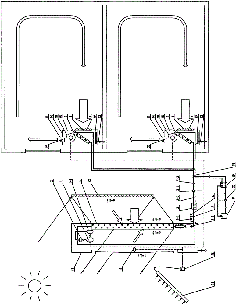
[0044] The embodiment of the air-solar composite source driven household heat pump air-conditioning and hot water unit proposed by the present invention is attached figure 1As shown, the description is as follows, which consists of: a scroll compressor 1 with a volume flow rate of 53m3 / h; a gas-liquid separator 1-1 with a port diameter of 38.10 mm; a four-way reversing valve 2 with a port diameter of 38.10 mm; heat exchange Use-side heat exchanger 3 with an area of ​​4m2; circulating water pump 3-1 with a flow rate of 8m3 / h and a lift of 27mH2O; check valve 3-2 with a port diameter of 50mm; filter 3-3 with a port diameter of 50mm; length 1069mm and height 620mm , Thickness 44mm, 2 rows of red copper pipe casing with corrugated window of 9.52mm in diameter, high-efficiency aluminum finned fluorine coil absorber 4; check valve 5 with interface diameter 15.88mm; high pressure liquid reservoir 5-1 with interface diameter 15.88mm; Expansion valve 6 with an interface diameter of 15....


PUM


Abstract

The invention discloses an air-solar-combining-source-driving household type heat pump air-conditioning water heating unit. The air-solar-combining-source-driving household type heat pump air-conditioning water heating unit is characterized in that (1) solar energy is absorbed through a reflecting mirror, transparent blades and black fin cavities, air energy is absorbed through fins, and the design that a solar absorber and an air fin evaporator are integrated is achieved; (2) the air-solar-combining-source-driving household type heat pump air-conditioning water heating unit is built to increase the evaporation temperature; (3) the condensation temperature is decreased in a vertically-upward air-curtain unified heating manner and an efficient air-conditioning tail end manner; (4) the heating amount and the energy efficiency ratio of a heat pump are increased by reducing the circulation temperature difference; and (5) the solar energy is used in an efficient and low-price photo-thermal conversion manner to drive the heat pump, and the application threshold of solar household type heat pump air-conditioning hot water is lowered.

Description

(1) Technical field [0001] The invention relates to a household heat pump air conditioner and hot water unit driven by an air-solar composite source. (2) Background technology [0002] The existing solar heat pump air conditioning and hot water units mainly have two product forms: [0003] 1. The heat pump evaporator is designed as a solar panel absorber: it is made of double-layer aluminum plates painted black on the surface facing the light, and the distributor and circulation pipe of Freon heat pump working fluid are formed between the double-layer aluminum plates; among them, the black-coated aluminum plates are used to absorb the sun. light and provide heat for evaporation, while distributors and flow ducts are used to optimize the evaporation process in the heat pump cycle. Since the intensity of sunlight received by each square meter area does not exceed 1kW, it greatly limits the improvement of the heating capacity of the heat pump; in addition, since this form of e...

Claims


Application Information

Patent Timeline
Patent Type & Authority Applications(China)
IPC IPC(8): F25B29/00
Inventor 侴乔力陈江侴雨宏魏蔚
Owner 侴乔力
Why Eureka
Try Eureka