
Vibration isolator

A technology of anti-vibration device and inner cylinder, which is applied in the direction of power plant, jet propulsion device, internal combustion propulsion device, etc., can solve the problem of low rigidity and achieve the effect of increasing the stop function

Active Publication Date: 2015-11-18
BRIDGESTONE CORP
View PDF6 Cites 7 Cited by
  • Summary
  • Abstract
  • Description
  • Claims
  • Application Information

AI Technical Summary

Problems solved by technology

Generally, the characteristics of such anti-vibration support devices in the front-rear direction of the vehicle are optimized, and the rigidity (spring constant) in the vertical direction of the vehicle or the left-right direction (inner cylinder axial direction) tends to be low.

Method used


Image

  • Vibration isolator
  • Vibration isolator
  • Vibration isolator

Examples


Embodiment Construction

[0020] Embodiments of the anti-vibration device of the present invention are illustrated and described below with reference to the drawings.

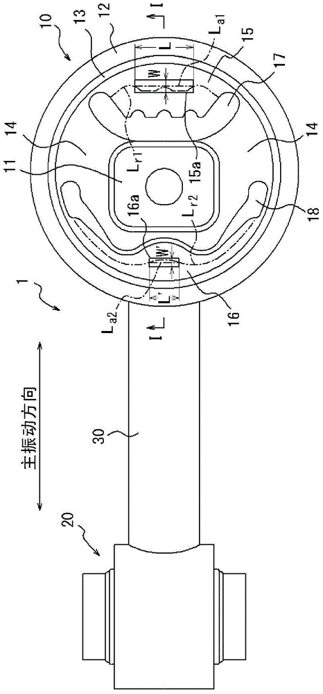
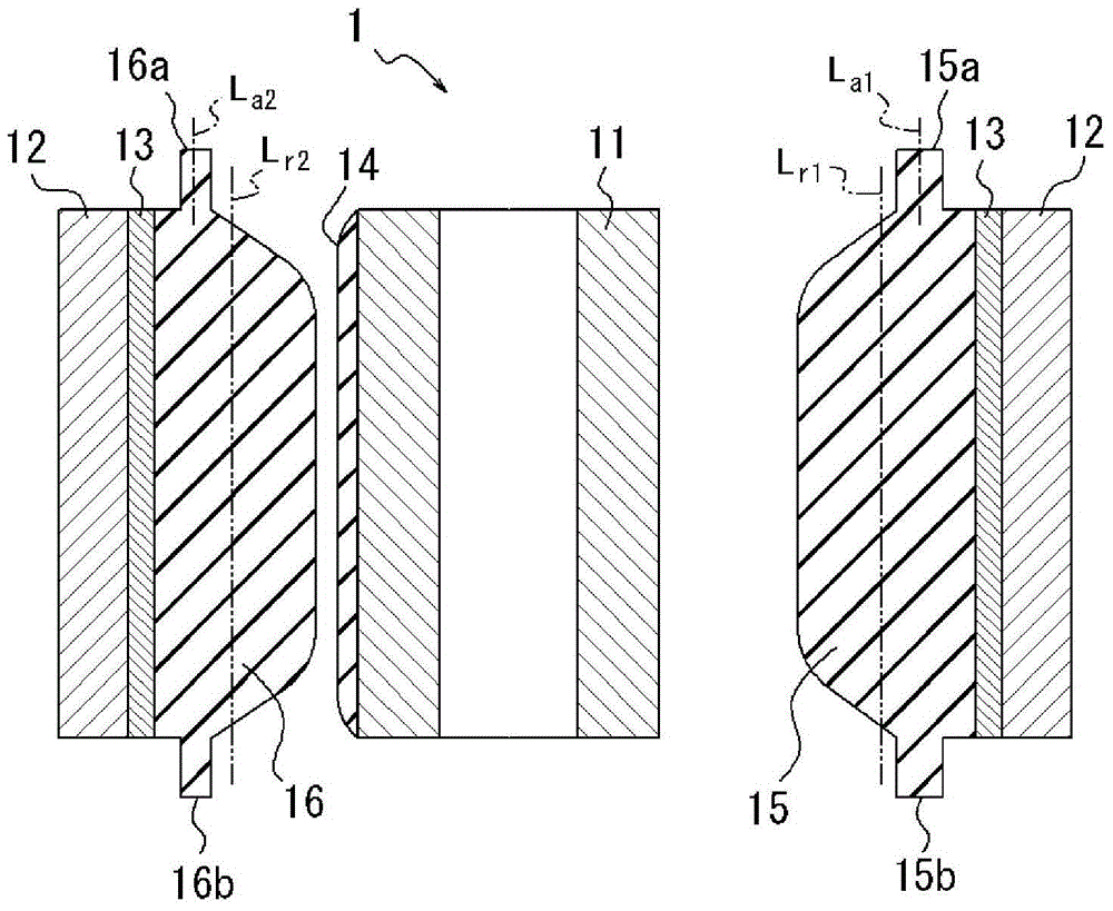
[0021] figure 1 with figure 2 The anti-vibration device 1 in the illustrated embodiment is a torsion bar, which includes a first elastic sleeve 10; a second elastic sleeve 20 whose diameter is smaller than that of the first elastic sleeve 10; and The connecting rod 30 connects the first elastic sleeve 10 and the second elastic sleeve 20 .

[0022] Such as figure 1 As shown, the first elastic sleeve 10 includes: an inner cylinder 11; a middle cylinder 13; a main body elastic body 14, which connects the inner cylinder 11 and the middle cylinder 13; a stopper elastic body (stopperelasticbody) 15, a stopper elastic body 15 is fixed on the middle cylinder 13 and in the axial direction with the inner cylinder 11 (with figure 1 The direction perpendicular to the surface of the paper, hereinafter also referred to as "inner cylinder axial d...


PUM


Abstract

The present invention has: an inner cylinder (11) coupled to either one of a vibration generator and a vibration receiver; an outer cylinder (12) coupled to the other of the vibration generator and the vibration receiver; an intermediate cylinder (13) fitted on the inner circumferential surface of the outer cylinder (12); a main elastic body (14) for connecting the inner cylinder (11) and the intermediate cylinder (13); and stopper elastic bodies (15, 16) that are fixed to the intermediate cylinder (13) and that face the inner cylinder (11), there being interposed therebetween at least hollow sections (17, 18) formed in a direction orthogonal to the inner cylinder shaft direction so as to penetrate the main elastic body (14) in the inner cylinder shaft direction so that the stopper elastic bodies (15, 16) remain independent of the main elastic body (14). The stopper elastic bodies (15, 16) respectively have shaft direction stopper sections (15a, 16a) that protrude more in the inner cylinder shaft direction than the intermediate cylinder (13) and the outer cylinder (12).

Description

technical field [0001] The present invention relates to an anti-vibration device used in automobiles and the like. Background technique [0002] As a vehicle anti-vibration device, for example, as described in Patent Document 1, a vibration-proof support device installed between a vibration generating part such as an engine and a vehicle body in the vehicle front-rear direction is known. Generally, the characteristics of such anti-vibration support devices in the front-rear direction of the vehicle tend to be low in rigidity (spring constant) in the vertical direction or left-right direction of the vehicle (inner cylinder axial direction). Therefore, for example, when the vehicle makes a sharp turn or crosses a bump, the outer cylinder of the anti-vibration support device may hit the vehicle body and generate a crash sound. [0003] In the anti-vibration support device described in Patent Document 1, rubber protrusions protruding outward from both ends in the axial directio...

Claims


Application Information

Patent Timeline
Patent Type & Authority Applications(China)
IPC IPC(8): F16F1/38B60K5/12F16F15/08
CPCF16F1/3828F16F1/3849F16F1/3814B60G13/04B60G2202/25B60G2500/10
Inventor 杉本幸大
Owner BRIDGESTONE CORP
Learn More