Valve lock clamp groove rolling device

A technology of a rolling device and a valve locking clip, which is applied in the field of valve processing equipment, can solve the problems of defective valve appearance, large surface roughness, large processing marks, etc.

Active Publication Date: 2015-11-25
安徽鼎立智能制造股份有限公司
View PDF5 Cites 13 Cited by
  • Summary
  • Abstract
  • Description
  • Claims
  • Application Information

AI Technical Summary

Problems solved by technology

[0002] The existing valve lock groove is turned on a lathe, but the surface roughness is relatively large, especially for the intake valve, the material of the inta

Method used


Image

  • Valve lock clamp groove rolling device
  • Valve lock clamp groove rolling device
  • Valve lock clamp groove rolling device

Examples


Embodiment Construction

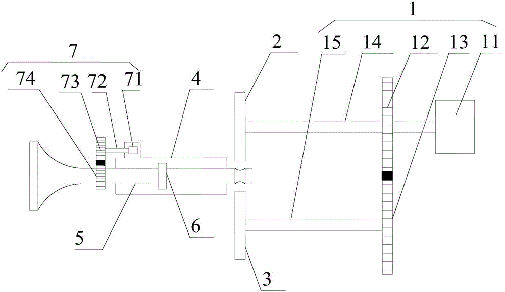
[0017] refer to figure 1 , the present invention proposes a rolling device for a valve lock clamp groove, comprising a driving mechanism 1, a first rolling wheel 2, a second rolling wheel 3, a valve support frame 4 and a controller, wherein:

[0018] The driving mechanism 1 comprises a first driving device 11, a first driving gear 12, a driven gear 13, a first transmission shaft 14, a second transmission shaft 15, the first driving gear 12 meshes with the driven gear 13, and the first driving gear 12 It is connected with the first driving device 11 , and the controller is connected with the first driving device 11 for controlling the rotation speed of the first driving gear 12 .

[0019] The first rolling wheel 2 and the second rolling wheel 3 are symmetrically arranged on both sides of one end of the valve support frame 4, the first rolling wheel 2 is centrally connected with the first driving gear 12 through the first transmission shaft 14, and the second rolling wheel 3 is...


PUM


Abstract

The invention provides a valve lock clamp groove rolling device. The valve lock clamp groove rolling device comprises a driving mechanism, a first rolling wheel, a second rolling wheel, a valve support frame and a controller, wherein the controller is connected to a first driving device and is used for controlling the rotational speed of a first driving gear; the first rolling wheel and the second rolling wheel are symmetrically arranged at the two sides of one end of the valve support frame; the first rolling wheel is connected to the center of the first driving gear through a first transmission shaft; the second rolling wheel is connected to the center of a driven gear through a second transmission shaft; both the first rolling wheel and the second rolling wheel can make feed movements toward the valve support frame; a first ring button for preventing a valve from deviating and a rotating device for driving the valve to rotate are arranged on the valve support frame; and the controller is connected to the rotating device and is used for controlling the rotational speed of the rotating device. The valve lock clamp groove rolling device can be used for machining a lock clamp groove to obtain relatively good surface roughness, causes the surface of the lock clamp groove to be smooth and flat and prolongs the service life of the lock clamp groove.

Description

technical field [0001] The invention relates to the technical field of valve processing equipment, in particular to a rolling device for a valve lock clamp groove. Background technique [0002] The existing valve lock groove is turned on a lathe, but the surface roughness is relatively large, especially for the intake valve, the material of the intake valve is soft, and the processing marks are relatively large, resulting in flaws in the appearance of the valve , have an impact on the effect of later use. Contents of the invention [0003] In order to solve the technical problems existing in the background technology, the present invention proposes a rolling device for the valve lock clamp groove, which can better process the surface roughness of the valve lock clamp groove, make the surface of the valve lock clamp groove smooth and smooth, and improve the service life. [0004] A rolling device for a valve lock clamp groove proposed by the present invention includes a d...

Claims


Application Information

Patent Timeline
IPC IPC(8): B23P9/02
CPCB23P9/02
Inventor 方阳光
Owner 安徽鼎立智能制造股份有限公司
Why Eureka
Try Eureka