FED pixel driver, FED display panel and display device

A technology of pixel driver and display panel, applied in the direction of instruments, static indicators, etc., can solve the problem of inability to precisely control the brightness of the emitting display

Active Publication Date: 2015-11-25
BOE TECH GRP CO LTD +1
View PDF6 Cites 0 Cited by
  • Summary
  • Abstract
  • Description
  • Claims
  • Application Information

AI Technical Summary

Problems solved by technology

[0009] Embodiments of the present invention provide a FED pixel driver, a FED display panel, and a display device, which can solve the problem that the brightness of a field emission display cannot be accurately controlled by adjusting the grid-cathode voltage.

Method used


Image

  • FED pixel driver, FED display panel and display device
  • FED pixel driver, FED display panel and display device
  • FED pixel driver, FED display panel and display device

Examples


Embodiment Construction

[0032] The following will clearly and completely describe the technical solutions in the embodiments of the present invention with reference to the accompanying drawings in the embodiments of the present invention. Obviously, the described embodiments are only some, not all, embodiments of the present invention. Based on the embodiments of the present invention, all other embodiments obtained by persons of ordinary skill in the art without making creative efforts belong to the protection scope of the present invention.

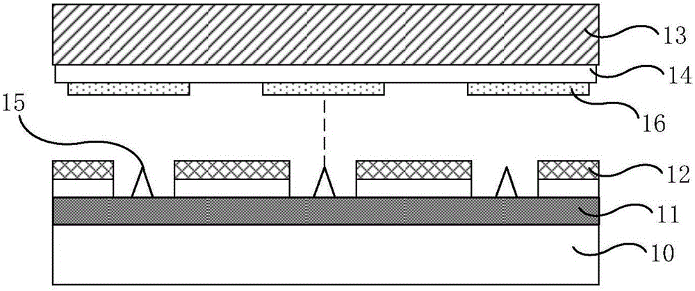
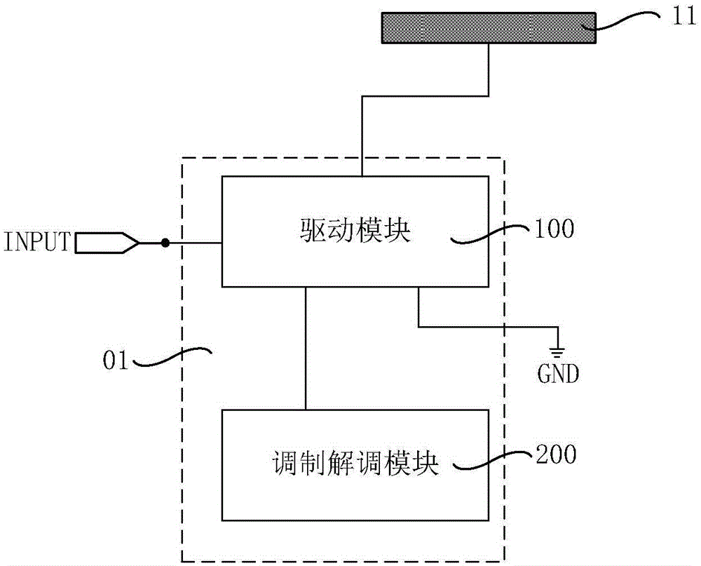
[0033] An embodiment of the present invention provides a FED pixel driver 01, and the FED includes a cathode 11 as shown in FIG. 1 , as Figure 2a As shown, the FED pixel driver 01 includes a driving module 100 and a modulation and demodulation module 200 .

[0034] The driving module 100 is connected to the modulation and demodulation module 200 for providing an on or off signal under the control of the modulation and demodulation module 200 .

[0035]The dr...


PUM


Abstract

Embodiments of the invention provide an FED (Field Emission Display) pixel driver, an FED display panel and a display device, and relate to the technical field of display. The FED pixel driver comprises a cathode, a drive module, and a modulation and demodulation module. The drive module is connected with the modulation and demodulation module, and is used for providing an opening or closing signal under the control of the modulation and demodulation module. The drive module is further connected with a reference potential input end used for providing reference potential, the cathode, and a grounding end, and is used for driving electrons of the cathode to escape and generate constant emission current in the open state under the control of the reference potential input end and the grounding end. The FED pixel driver, the FED display panel and the display device are used in display.

Description

technical field [0001] The invention relates to the field of display technology, in particular to an FED pixel driver, an FED display panel, and a display device. Background technique [0002] Field emission display (English: Field Emission Display, English abbreviation: FED) is adopted, which can combine the high display quality of CRT (Chinese: Cathode Ray Tube, English: Cathode Ray Tube) display and the low In addition, field emission displays are more and more applied to the field of display technology because of their small size, high brightness, large viewing angle, high resolution, wide operating temperature range, and low power consumption. . [0003] Field emission displays in the prior art, such as Figure 1a As shown, it includes a cathode 11 and a gate electrode 12 sequentially located on the lower substrate 10 , and an anode 14 located on the upper substrate 13 . When a certain electric field is applied between the gate electrode 12 and the cathode 11, a large...

Claims


Application Information

Patent Timeline
Patent Type & Authority Applications(China)
IPC IPC(8): G09G3/22
Inventor 张志豪孙志华张旭张洪林李承珉
Owner BOE TECH GRP CO LTD
Why Eureka
Try Eureka