honey shaker

A technology for shaking honey and storing honey, which is applied in honey harvesting, fumigation, devices for catching or killing insects, etc. It can solve the problems of easy entry and death of bees, and achieve the convenience of putting incense sticks, reducing economic losses, and avoiding The effect of bee death

Active Publication Date: 2017-06-23
武汉市华明达蜂业有限公司
View PDF8 Cites 2 Cited by
  • Summary
  • Abstract
  • Description
  • Claims
  • Application Information

AI Technical Summary

Problems solved by technology

[0003] The technical problem to be solved by the present invention is to provide a honey shaker capable of repelling bees, so as to solve the problem that bees in existing honey shakers are easy to enter and cause death

Method used


Image

  • honey shaker
  • honey shaker
  • honey shaker

Examples


Embodiment Construction

[0021] The present invention will be described in further detail below in conjunction with accompanying drawing embodiment:

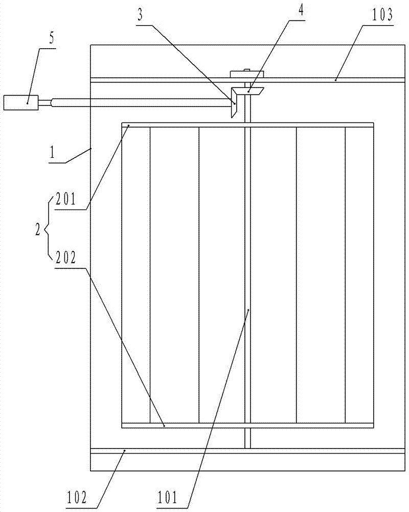
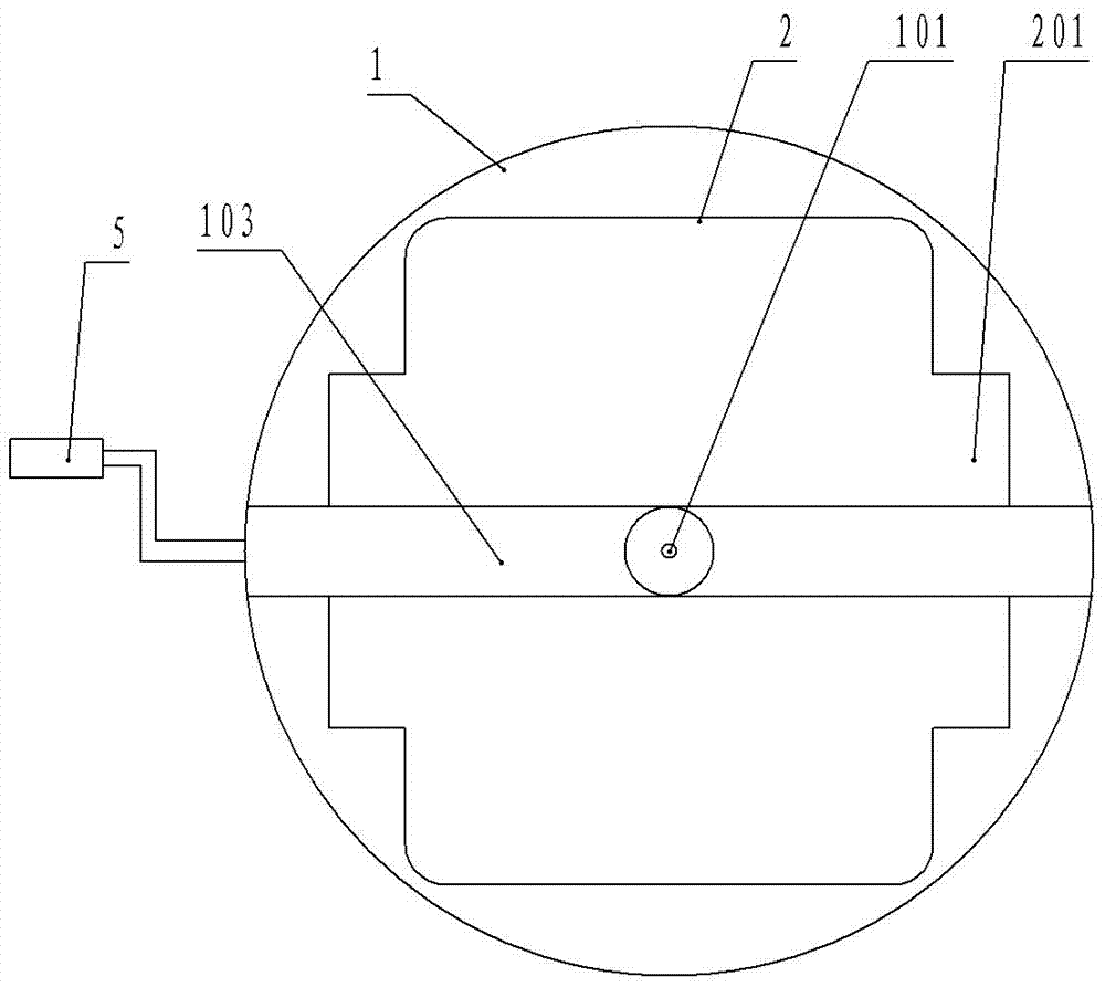
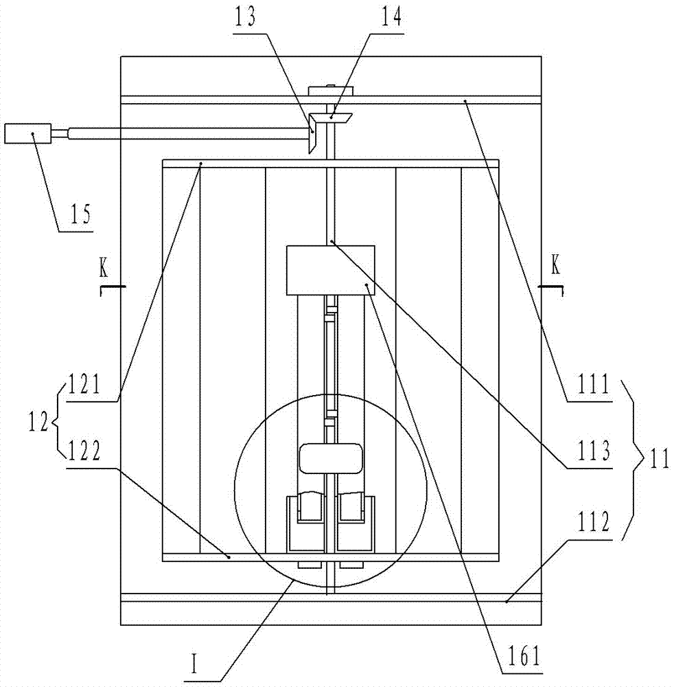
[0022] image 3 , Figure 4 , Figure 5 , Figure 6 , Figure 7 , Figure 8 , Figure 9 The shown honey shaker includes a honey bucket 11 and a honey shaker frame 12 arranged in the honey bucket 11, an upper beam 111 and a lower beam 112 are respectively connected between the inner walls of the honey bucket 11, and the upper beam 111 and the The lower crossbeam 112 is respectively provided with coaxial bearings; shakes the honey frame 12 and includes a ring-shaped upper frame, a ring-shaped bottom frame and a plurality of poles arranged between the ring-shaped upper frame and the ring-shaped bottom frame. A groove 123 for installing honeycombs is arranged in the space surrounded by the ring-shaped bottom frame and the support rods, an upper stay 121 is connected between the ring-shaped upper frames, a lower stay 122 is connected between the ring-s...


PUM


Abstract

The invention discloses a honey extractor, belonging to the technical field of honey collecting appliances. The honey extractor comprises a honey extracting framework, wherein the honey extracting framework is arranged in a honey containing barrel through a rotating shaft; a groove for installing a honeybee comb is formed in the honey extracting framework; the honey extracting framework is provided with an upper supporting rod and a lower supporting rod; an upper cross beam and a lower cross beam are respectively connected between the inner walls of the honey containing barrel; one end of the rotating shaft is arranged on the upper cross beam in a penetrating way by penetrating through the upper supporting rod; the other end of the rotating shaft is arranged on the lower cross beam in the penetrating way by penetrating through the lower supporting rod; the lower supporting rod is provided with a honeybee driver which is connected to the rotating shaft in a clamping way. According to the honey extractor disclosed by the invention, the problem of an existing honey extractor that honeybees are easy to get in the existing honey extractor to cause death can be solved.

Description

technical field [0001] The invention relates to the technical field of making honey shakers, in particular to a honey shaker capable of repelling bees. Background technique [0002] The honey shaker is an important tool for extracting honey; figure 1 , figure 2 The shown honey shaker includes a honey bucket 1 and a honey shaker frame 2 installed in the honey bucket 1 through a rotating shaft 101. The honey shaker frame 2 includes an annular upper frame with an upper strut 201 and a lower strut. 202 ring-shaped bottom frame, the upper beam 103 and the lower beam 102 are respectively connected between the inner walls of the honey bucket 1, one end of the rotating shaft 101 passes through the upper strut 201 and is mounted on the upper beam 103, and the other end of the rotating shaft 101 passes through The lower support rod 202 is mounted on the lower beam 102, the honey shaker frame 2 has a groove 201 for installing the honeycomb, and the rotating shaft 101 is provided wit...

Claims


Application Information

Patent Timeline
Patent Type & Authority Patents(China)
IPC IPC(8): A01K59/00A01M13/00
CPCA01K59/00A01M13/00
Inventor 廖才生
Owner 武汉市华明达蜂业有限公司
Why Eureka
Try Eureka