Supercharge Your Innovation With Domain-Expert AI Agents!

Overhead type current transformer sheath capable of being stacked

A current transformer and energy barrier technology, which is applied to the container, container, rigid container of the machine, etc., can solve the problem of large space, unfavorable access to the sheath, and inconvenience for placing other types of current transformers or other items. and other problems, to achieve the effect of saving location space and highly flexible design

Inactive Publication Date: 2015-12-02
NANJING JIARUISI ELECTRIC POWER TECH
View PDF6 Cites 0 Cited by
  • Summary
  • Abstract
  • Description
  • Claims
  • Application Information

AI Technical Summary

Problems solved by technology

[0003] The shape of the traditional overhead current transformer sheath is basically the same as that of the overhead current transformer. Since the overhead current transformer does not have a fixed standing surface, it needs to be specially customized to place the overhead current transformer during storage or transportation. The shelf of the transformer sheath increases the transportation or storage cost of the overhead current transformer, and the shelf dedicated to the overhead current transformer sheath is not convenient for placing other styles of current transformers or other items, which is very important for the use of the shelf Bring certain limitations, not conducive to the full utilization of resources
[0004] Moreover, the traditional overhead current transformer sheath cannot be stacked, and can only be placed in a single layer, which takes up a lot of space
When the traditional overhead current transformer sheath is placed on the shelf, the upper and lower adjacent shelves are too close to be conducive to picking and placing the sheath, and too far away, resulting in a waste of space

Method used


Image

  • Overhead type current transformer sheath capable of being stacked
  • Overhead type current transformer sheath capable of being stacked
  • Overhead type current transformer sheath capable of being stacked

Examples


Embodiment Construction

[0020] The present invention will be further explained below in conjunction with the accompanying drawings and specific embodiments. It should be understood that the following specific embodiments are only used to illustrate the present invention but not to limit the scope of the present invention.

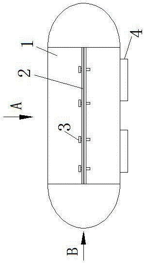
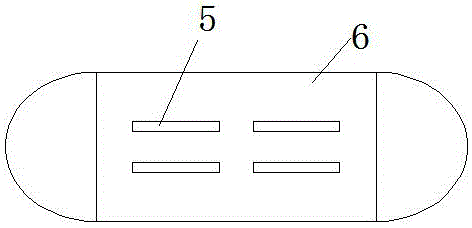
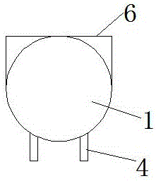
[0021] It can be seen from the accompanying drawings that the sheath of the overhead current transformer with intrinsic energy barriers includes a casing 1, a platform 6 is arranged on the outside of the casing 1, and several The leg 4, an opening is provided between the leg 4 and the platform 6, and the opening extends from one end of the casing 1 to the other end. In the present invention, the cover body 1 is used to install an overhead current transformer, and the legs 4 are used to support the cover body 1 to stand on a flat surface, so as to prevent the cover body 1 from being unable to stand stably on a flat surface, and it is necessary to use a special shelf or other The t...


PUM


Abstract

The invention relates to an overhead type current transformer sheath capable of being stacked. The overhead type current transformer sheath comprises a sheath body, wherein a platform is arranged at the outer part of the sheath body, and a plurality of supporting feet are arranged the outer part of the sheath body on the opposite side of the platform; openings are formed between the supporting feet and the platform, and each open extends from one end of the sheath body to the other end of the sheath body. The overhead type current transformer sheath can stacked for multiple layers, so that a shelf used for storing the sheath can be simplified, the height design of the adjacent upper and lower layers of the shelf is more flexible, and the position space occupied by the sheath can be saved through stacking. The sheath on the upper layer is inserted into buckling grooves in the platform of the sheath on the lower layer through the supporting feet, so that the connection of the upper-layer sheath and the lower-layer sheath is stable.

Description

technical field [0001] The invention relates to an overhead current transformer sheath for energy barrier discharge, and belongs to the technical field of current transformers. Background technique [0002] A current transformer is a precision instrument. During transportation or storage, the current transformer is usually placed in the matching current transformer sheath. [0003] The shape of the traditional overhead current transformer sheath is basically the same as that of the overhead current transformer. Since the overhead current transformer does not have a fixed standing surface, it needs to be specially customized to place the overhead current transformer during storage or transportation. The shelf of the transformer sheath increases the transportation or storage cost of the overhead current transformer, and the shelf dedicated to the overhead current transformer sheath is not convenient for placing other styles of current transformers or other items, which is very...

Claims


Application Information

Patent Timeline
Patent Type & Authority Applications(China)
IPC IPC(8): B65D21/032B65D85/68
Inventor 何斌何宜霖刘红斌陈先军杨启超周芬娄洪周
Owner NANJING JIARUISI ELECTRIC POWER TECH
Features
  • R&D
  • Intellectual Property
  • Life Sciences
  • Materials
  • Tech Scout
  • Unparalleled Data Quality
  • Higher Quality Content
  • 60% Fewer Hallucinations
Learn More