Supercharge Your Innovation With Domain-Expert AI Agents!

Disk drive apparatus

Inactive Publication Date: 2006-01-31
WESTERN DIGITAL TECH INC
View PDF7 Cites 1 Cited by
  • Summary
  • Abstract
  • Description
  • Claims
  • Application Information

AI Technical Summary

Benefits of technology

[0014]The above configuration allows the highly rigid supporting arm to rotate about the bearing section in a direction perpendicular to the recording face of the recording medium. Since the supporting arm is highly rigid, no vibration occurs in the L / UL system, and thus makes stable L / UL operation feasible. Moreover, this configuration offers high design flexibility with respect to the disk drive apparatus, enabling downsizing. Furthermore, the ramp, which executes the L / UL operation, can be disposed in a position that does not interfere with the disk surface. This offers a highly reliable disk drive apparatus without foreign particles being generated by contact between the supporting arm and ramp.

Problems solved by technology

This results in mechanical and magnetic damage to recording medium 107 when restarting.
If the suspension is configured with a thin plate to give flexibility to the head support assembly, unstable phenomena such as vibration by bending or torsion occurs in the head support assembly.
Accordingly, the following disadvantage is found in adopting the L / UL system with the above suspension structure.
L / UL operation becomes unstable due to vibration of the suspension because the guide is provided at the tip of the low-rigidity suspension and this guide is slid up a tapered ramp.
This results in loss of design flexibility.
In addition, downsizing of the disk drive apparatus becomes difficult because the L / UL mechanism is provided at the tip of the head supporting arm.
This is an impediment to the efficient use of the surface of magnetic recording medium, particularly when the size is reduced.

Method used


Image

  • Disk drive apparatus
  • Disk drive apparatus
  • Disk drive apparatus

Examples


first exemplary embodiment

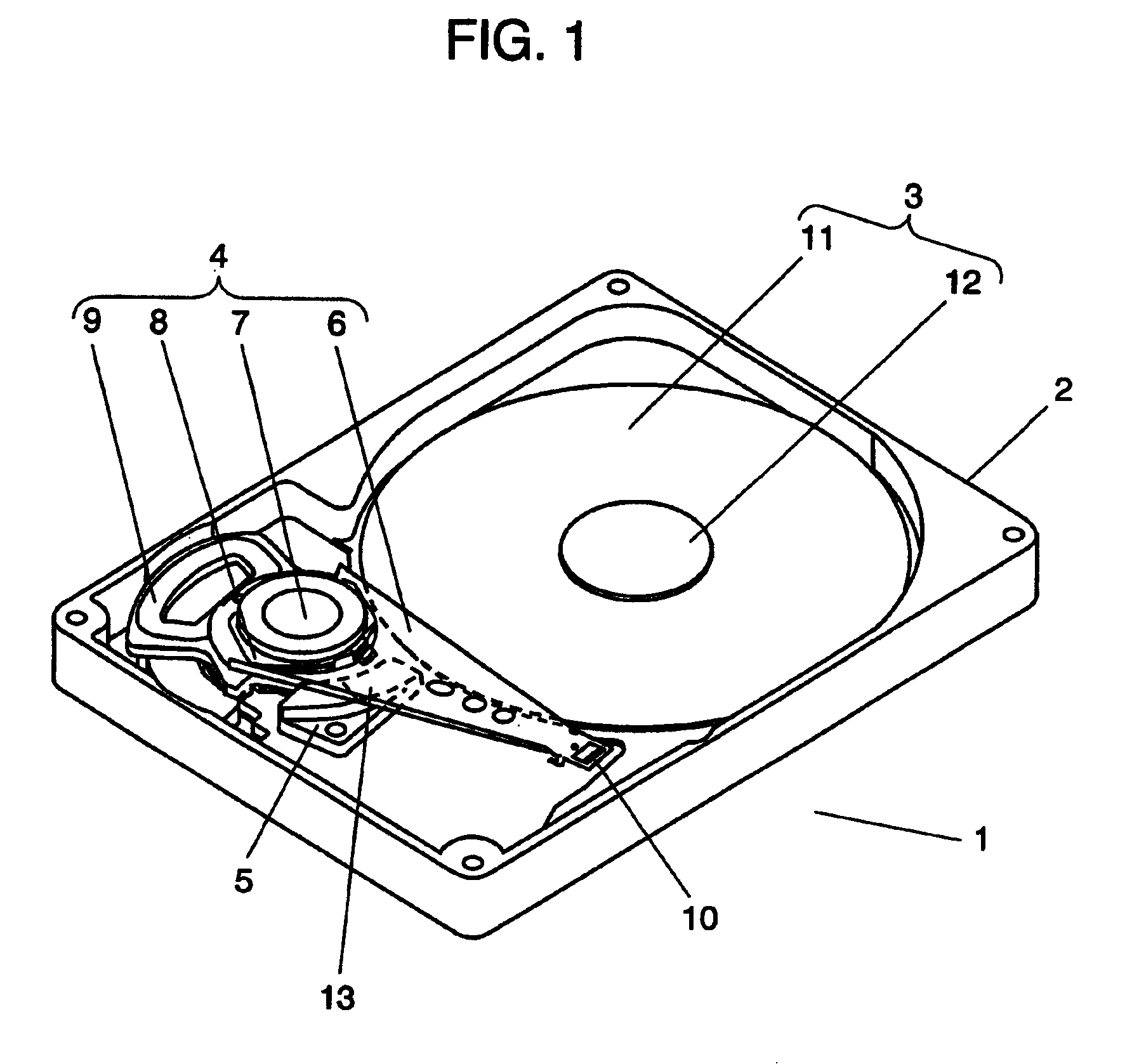
[0024]FIG. 1 is a perspective view of a disk drive apparatus in a first exemplary embodiment of the present invention.

[0025]FIG. 1 illustrates the state where a supporting arm is resting on a ramp in the L / UL system, which means that the magnetic head is unloaded.

[0026]Disk drive apparatus 1 includes housing 2, disk unit 3, head actuator 4, and ramp 5.

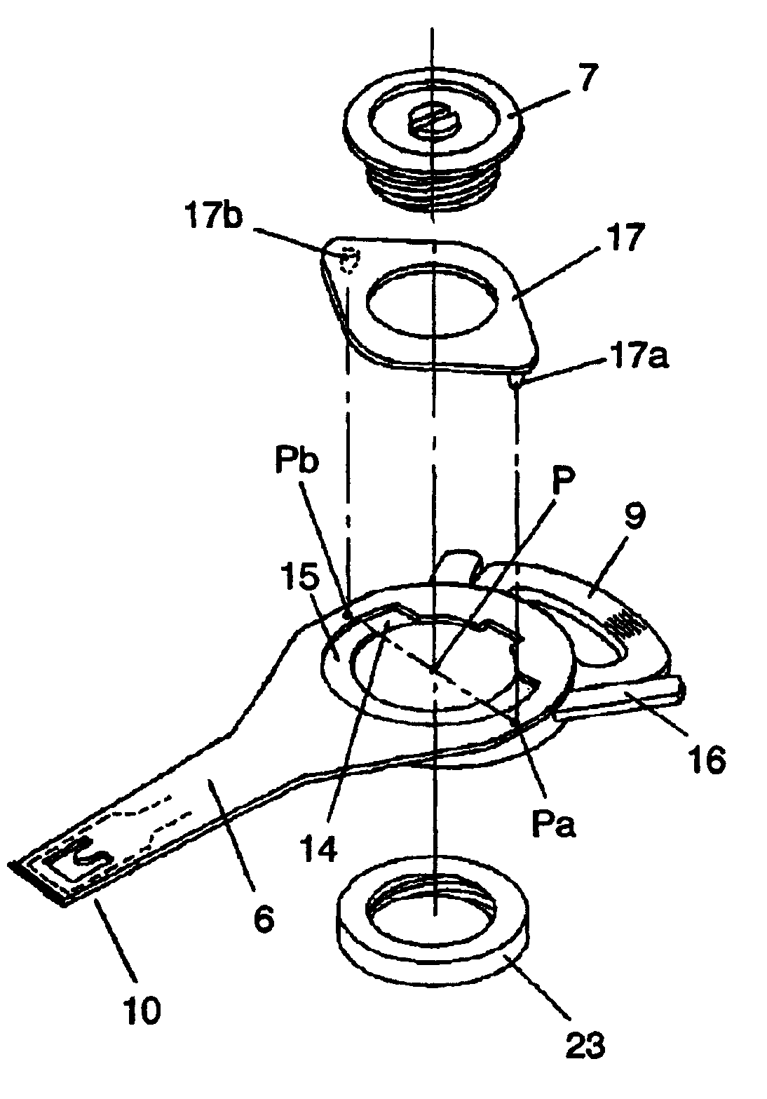
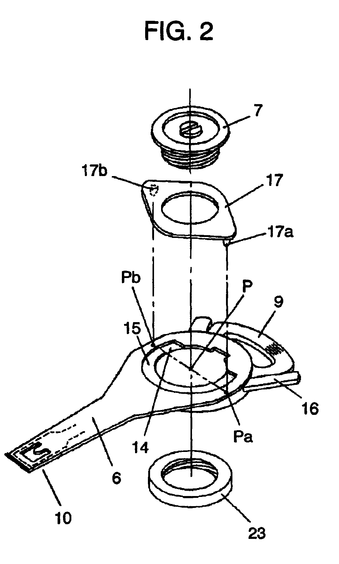
[0027]Head actuator 4 includes supporting arm 6, first bearing 7, second bearing 8, coil 9, and VCM (Voice Coil Motor) configured such as a yoke (not illustrated). Slider 10 on which the head element (not illustrated) for recording and playback is disposed is attached to a tip of supporting arm 6 in a way such that slider 10 faces magnetic recording medium 11 in disk unit 3. Supporting arm 6 rotates about first bearing 7 in a radial direction of magnetic recording medium 11. In addition, supporting arm6 is configured rotatably about second bearing 8 in a direction perpendicular to the surface of magnetic recording medium 11 in what is ...

second exemplary embodiment

[0040]FIG. 4 is a perspective view of a disk drive apparatus in a second exemplary embodiment employing the L / UL system.

[0041]The configuration of the disk drive apparatus in FIG. 4 is basically the same as that of the disk drive apparatus in FIG. 1. The point which differs is that ramp 20, where supporting arm 6 is moved, is disposed near slider 10 of supporting arm 6. In addition, a part of ramp 20 is disposed so as to protrude toward magnetic recording medium 11 in disk unit 3.

[0042]The second exemplary embodiment enables slider 10 to move to the standby position by a part near slider 10 of supporting arm 6. This further ensures stable unloading.

third exemplary embodiment

[0043]FIG. 5 is a perspective view of a disk drive apparatus in a third exemplary embodiment of the present invention employing the CSS system.

[0044]In the CSS system, the surface of the predetermined zone on the disk recording medium in the disk unit to which the head is moved is roughened and divided from the recording zone to prevent adhesion of the magnetic head to the magnetic recording medium when the rotation of the magnetic recording medium is stopped. This has been hindering progress in increasing the memory capacity of magnetic recording media, and also reducing the efficiency of disk processing.

[0045]In the third exemplary embodiment, the supporting arm is lifted and held when the rotation of the magnetic recording medium is stopped to solve the disadvantage of the CSS system. Parts of the disk drive apparatus shown in FIG. 5 are the same as those in FIGS. 1, 2, and 3, and thus they are given the same reference numerals.

[0046]FIG. 5 illustrates the state that the head is ...


PUM


Abstract

A disk drive apparatus having a head support device with high impact resistance which ensures L / UL operation and CSS operation. The disk drive apparatus includes a supporting arm rotating about a bearing in a direction perpendicular to a recording face of a recording medium; and a ramp provided at any position between the bearing and a head of the supporting arm. The ramp vertically moves the supporting arm while the supporting arm rotates or linearly moves in a radial direction of the magnetic recording medium.

Description

FIELD OF THE INVENTION[0001]The present invention relates to disk drive apparatuses employing a levitation-type head, such as magnetic disk drive apparatuses, optical disk drive apparatuses, and magneto-optical disk drive apparatuses that have a head support mechanism.BACKGROUND OF THE INVENTION[0002]A sharp expansion of the market for portable electronic equipment (e.g. PDAs and mobile phones) and downsizing of these apparatuses have resulted in demands for greater portability, i.e., smaller, thinner models with higher impact resistance, for disk drive apparatuses which act as data storage means for mobile digital equipment. A range of methods have been proposed to disk drive apparatuses with the aim of achieving improved impact resistance.[0003]One example of a conventional disk drive apparatus employing a Flying-type head or flying head in a magnetic recording and reproducing apparatus, such as a hard disk drive apparatus, is described below with reference to the drawings.[0004]F...

Claims


Application Information

Patent Timeline
IPC IPC(8): G11B5/54G11B5/55G11B21/21G11B5/60G11B21/12G11B21/22
CPCG11B5/54G11B5/6005G11B5/5526
Inventor UENO, YOSHIHIROKUWAJIMA, HIDEKIMIYAMOTO, MAKOTO
Owner WESTERN DIGITAL TECH INC
Features
  • R&D
  • Intellectual Property
  • Life Sciences
  • Materials
  • Tech Scout
  • Unparalleled Data Quality
  • Higher Quality Content
  • 60% Fewer Hallucinations
Learn More