Refrigerating apparatus

a technology of refrigerating apparatus and refrigeration chamber, which is applied in the direction of refrigeration safety arrangement, refrigeration components, lighting and heating apparatus, etc., can solve the problems of prone to flushing phenomenon, high pressure loss, and risk of liquid refrigerant re-evaporation, and achieve stable operating state and high operating efficiency

Inactive Publication Date: 2007-05-17
HITACHI APPLIANCES INC
View PDF8 Cites 30 Cited by
  • Summary
  • Abstract
  • Description
  • Claims
  • Application Information

AI Technical Summary

Benefits of technology

[0018] According to the refrigerating apparatus of this invention, since the degree of supercooling of liquid refrigerant can be controlled irrespective of the circulating volume of refrigerant in the refrigeration cycle, it is possible to obtain a stable operating state and high operating efficiency.

Problems solved by technology

Therefore, if the liquid-refrigerant does not retain a sufficient degree of supercooling there is a risk of the liquid refrigerant re-evaporating (hereafter, referred to as “flush phenomenon”) due to pressure loss or the like in the liquid refrigerant piping that follows the condenser.
Further, since the circulating volume flow rate of an HFC refrigerant increases compared to, for example, R-22, the volume of refrigerant increases, pressure loss rises, and a flush phenomenon is liable to occur.
Examples of problems when a flush phenomenon occurs in liquid refrigerant piping in the refrigeration cycle include a noticeable drop in refrigerating capacity and overfilling of refrigerant when performing an operation to fill refrigerant while viewing the status of flush gas occurrence with a sight glass when performing trial operation for a unit.
However, the circulating amount of refrigerant varies greatly when this kind of capacity control is performed.
However, no studies have been carried out heretofore regarding this point.
More specifically, with respect to the high pressure liquid refrigerant and decompressed refrigerant flowing through the supercooling heat exchanger, since the decompressed refrigerant occupies a greater part of the flow ratio, the heat exchange efficiency of the supercooling heat exchanger decreases and evaporation of the decompressed refrigerant in the supercooling heat exchanger is insufficient.
Further, in the supercooling heat exchanger, there is a risk of a freeze burst occurring due to overcooling, and a refrigerant gas leak or the like being generated as a result thereof.

Method used


Image

  • Refrigerating apparatus
  • Refrigerating apparatus
  • Refrigerating apparatus

Examples


Embodiment Construction

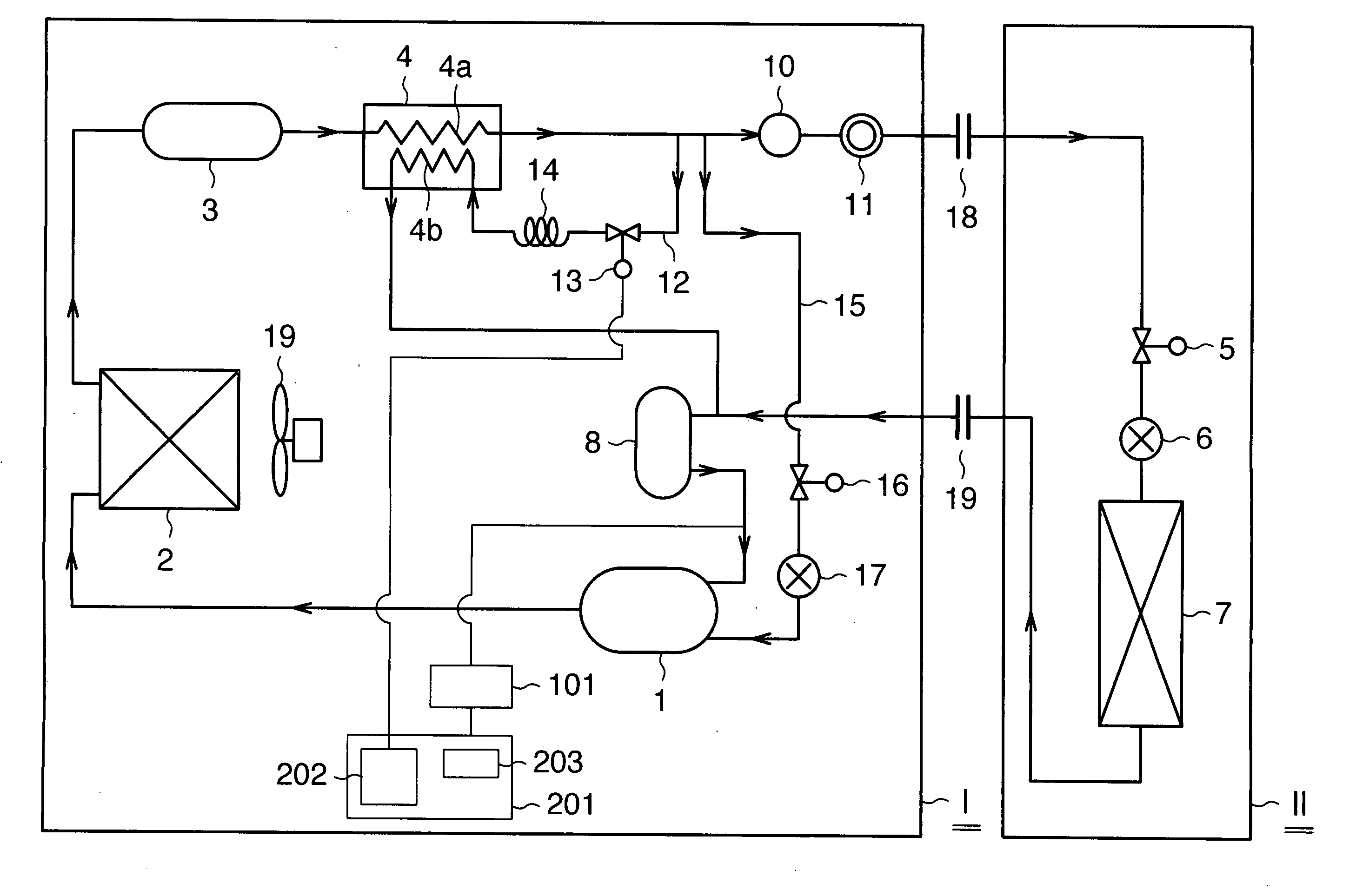
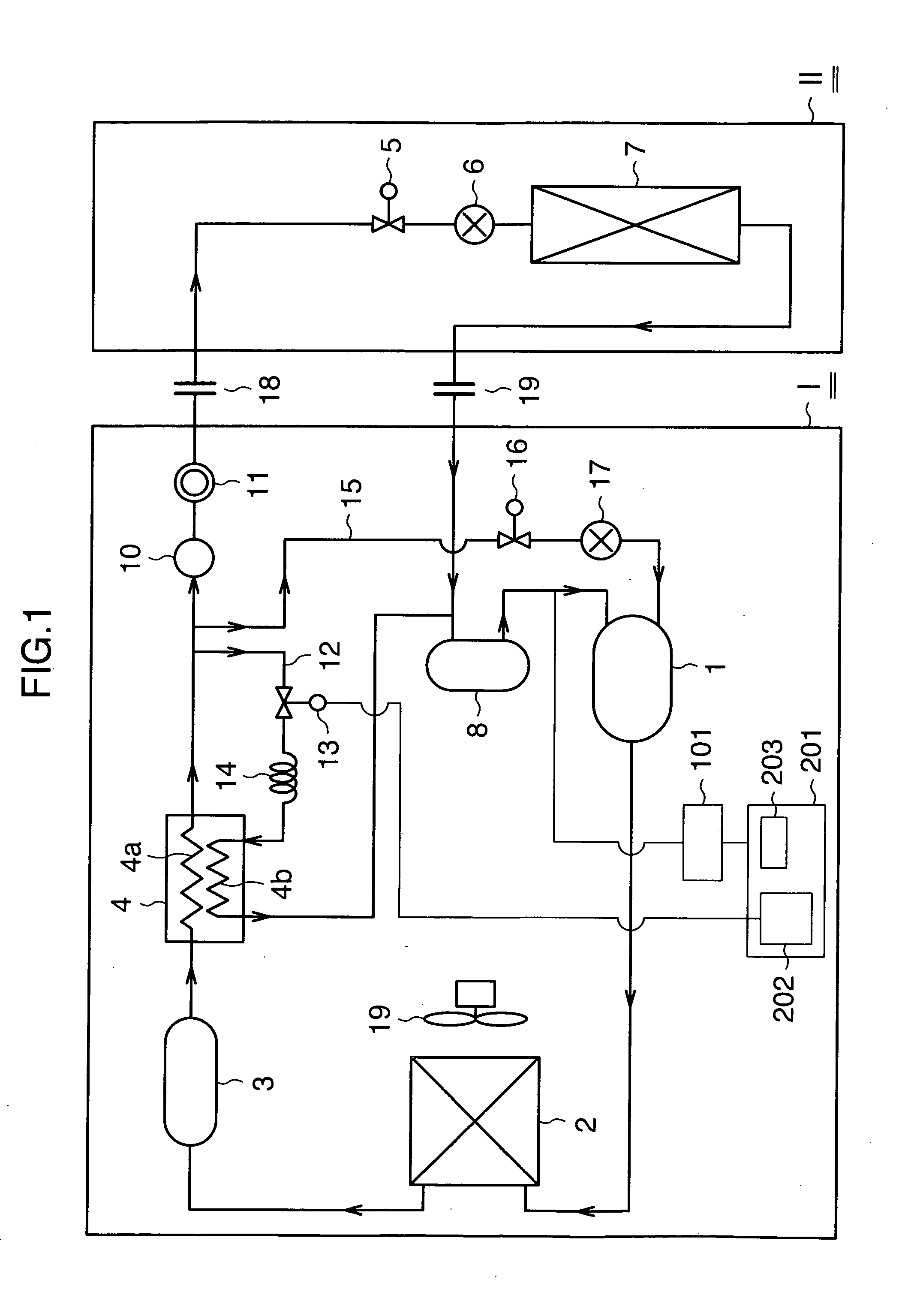
[0024] Hereunder, embodiments of the refrigerating apparatus of this invention are described using the attached drawings. FIG. 1 is a block diagram that shows the refrigeration cycle of a refrigerating apparatus applying this invention.

[0025] In this figure, the refrigerating apparatus of the present embodiment comprises a refrigeration cycle and a control apparatus. The refrigeration cycle has an air-cooled integrated type refrigerating apparatus I and a low-pressure side device II connected to the apparatus I.

[0026] The air-cooled integrated type refrigerating apparatus I comprises an accumulator 8, a compressor 1, a condenser 2, a liquid receiver 3, a supercooling heat exchanger 4, a dryer 10, and a sight glass 11 that are connected in this order by refrigerant piping, and a cooling fan 9 is disposed in the vicinity of the condenser 2. The low-pressure side device II comprises a solenoid valve 5, an expansion valve 6 and an evaporator 7 that are connected in this order by refri...


PUM


Abstract

To provide a refrigerating apparatus that can control the supercooling degree of liquid refrigerant irrespective of changes in circulating refrigerant amounts in a refrigeration cycle, a refrigerating apparatus includes a refrigeration cycle having one or more compressors or inverter compressor, a condenser, an expansion valve, and an evaporator; a liquid introduction circuit that guides decompressed refrigerant obtained by extracting one part of high pressure liquid refrigerant from the refrigeration cycle and decompressing, to a supercooling heat exchanger provided in the refrigeration cycle to perform heat transfer between the decompressed refrigerant and high pressure liquid refrigerant, and then introduces the refrigerant into refrigerant for intake into the compressors or inverter compressor or an intermediate pressure part of these compressors; a controller controlling shutdown of the compressors or driving frequencies of the inverter compressor based on suction pressure detection values with respect to pressure setting values for suction pressure of the compressors or inverter compressor; and a flow controller controlling the amount of high pressure liquid refrigerant flowing through the liquid introduction circuit based on the circulating volume of refrigerant in the refrigeration cycle.

Description

INCORPORATION BY REFERENCE [0001] The present application claims priority from Japanese application JP2005-330167 filed on Nov. 15, 2005, the content of which is hereby incorporated by reference into this application. BACKGROUND OF THE INVENTION [0002] (1) Field of the Invention [0003] The present invention relates to a refrigerating apparatus, and more particularly to technology for controlling the degree of supercooling of liquid refrigerant in a refrigeration cycle. [0004] (2) Description of Related Art [0005] Conventionally, a refrigerating apparatus uses a refrigeration cycle configured by connecting a compressor, a condenser, an expansion valve and an evaporator in this order by refrigerant piping. [0006] In this refrigeration cycle, after low pressure refrigerant that was drawn into the compressor is compressed to a predetermined high pressure, the refrigerant is guided to the condenser and changed into high pressure liquid refrigerant, by the heat exchange with air. This hig...

Claims


Application Information

Patent Timeline
Patent Type & Authority Applications(United States)
IPC IPC(8): F25B49/00F25B1/10
CPCF25B9/006F25B31/008F25B2400/075F25B2400/13F25B2500/27F25B2600/021F25B2700/1933Y02B30/741Y02B30/70
Inventor SAKURAI, TAKASHIOHTA, KAZUMASA
Owner HITACHI APPLIANCES INC
Why Eureka
Try Eureka