Mounting structure for light incidence end face of automobile light guide bar

A technology of light guide strips and light entrance ends, applied in optics, light guides, motor vehicles, etc., can solve the problems of reduced work efficiency, reduced production efficiency, inaccurate positioning, etc., and achieves the effects of simple structure, improved production efficiency, and convenient installation.

Inactive Publication Date: 2015-12-02
WUHU ANRUI OPTOELECTRONICS
View PDF5 Cites 4 Cited by
  • Summary
  • Abstract
  • Description
  • Claims
  • Application Information

AI Technical Summary

Problems solved by technology

[0002] With the widespread application of light guide technology in automotive lamps, the installation structure of light guides is becoming more and more complicated, which brings many difficulties to production
If the light guide is fixed to the decorative frame first, and then assembled with the lampshade to form the lampshade sub-assembly, then the lampshade sub-assembly is combined with the lamp housing glue groove, and there will be a power cord dragging it, regardless of whether the glue groove combination process is manual assembly , or mechanical assembly of tooling, the disposal of the power cord will reduce work efficiency; if the light guide end face fixer is not fixed on the decorative frame, but fixed in the inner lamp housing first, then when the lampshade sub-assembly is combined with the lamp housing glue groove , it is necessary to find the light guide end face fixer first, and then combine the glue groove. It cannot be installed blindly, which makes the positioning of the light guide light end face difficult and inaccurate, thereby reducing production efficiency

Method used


Image

  • Mounting structure for light incidence end face of automobile light guide bar

Examples


Embodiment Construction

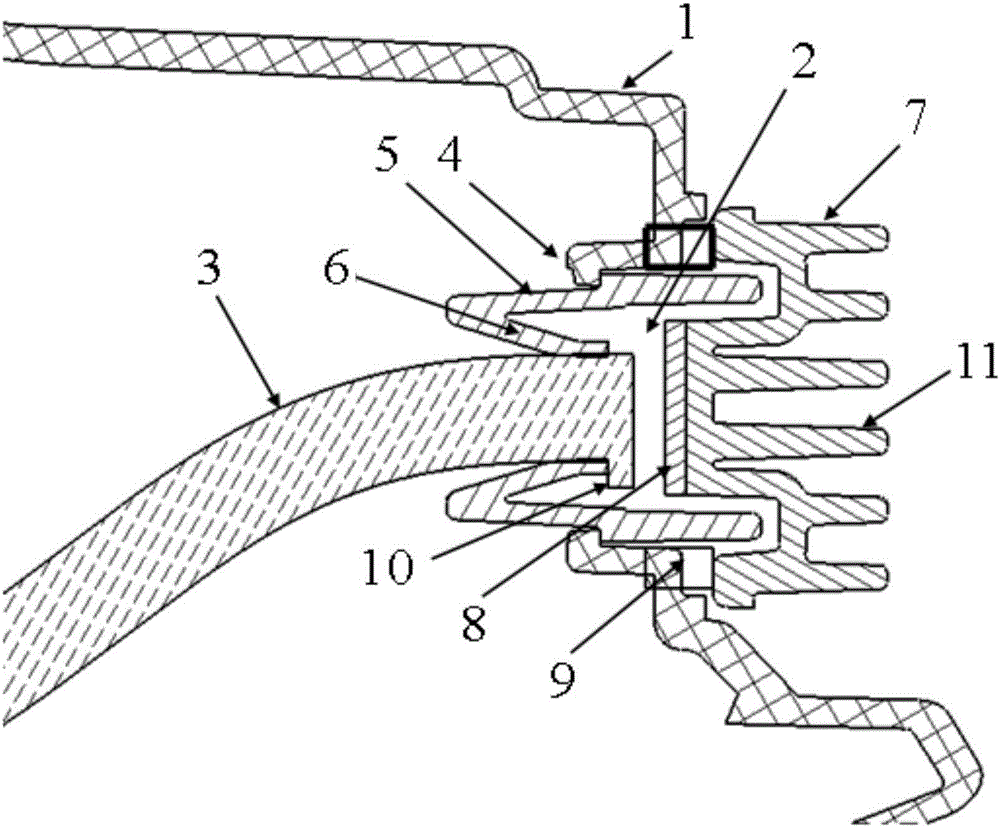
[0015] Such as figure 1 The light-incident end surface installation structure of a light guide strip for automobiles shown includes a lamp housing 1, a through hole 2 is arranged on the lamp housing 1, a light source module is arranged on one side of the through hole 2, and a light source module is arranged on the other side Install the light guide strip 3; the inner wall of the through hole 2 is provided with a fixing device for installing the light guide strip fixing part 5, and the through hole 2 is located on the side of the light guide strip 3 and is provided with a card for clamping the fixing device Point 4.

[0016] The fixing device includes a fixing part 5 that is clamped on the inner wall of the through hole 2 , and a clamping part 6 that extends inwardly from the fixing part 5 and is engaged with the end surface of the light guide strip 3 . Preferably, the fixing part 5 is in the shape of a tube, and the engaging part 6 extends from one end of the fixing part 5 to...


PUM


Abstract

The invention discloses a mounting structure for a light incidence end face of an automobile light guide bar, and belongs to the technical field of automobile accessories. The mounting structure comprises a lamp shell which is provided with a through hole, a light source module is arranged on one side of the through hole, and the light guide bar is arranged on the other side of the through hole; a fixing device used for clamping the end face of the light guide bar is arranged on the inner side wall of the through hole, and clamping points used for clamping the fixing device are arranged on the side of the light guide bar of the through hole. The fixing device comprises a fixing portion and a clamping portion, wherein the fixing portion is clamped on the inner side wall of the through hole, and the clamping portion extends to the inner side from the fixing portion and is clamped with the end face of the light guide bar. The mounting structure is simple and convenient to mount; the problem of a power line when the light guide bar and the light source module are mounted together is solved through the fixing device, the problem that the end face of the light guide bar is hard to position when the light guide bar and a lamp shell subassembly are mounted is solved, and the production efficiency and the product stability are improved.

Description

technical field [0001] The invention relates to a light-incident end surface installation structure of an automobile light guide strip, which belongs to the technical field of automobile accessories. Background technique [0002] With the widespread application of light guide technology in automotive lamps, the installation structure of light guides is becoming more and more complicated, which brings many difficulties to production. If the light guide is fixed to the decorative frame first, and then assembled with the lampshade to form the lampshade sub-assembly, then the lampshade sub-assembly is combined with the lamp housing glue groove, and there will be a power cord dragging it, regardless of whether the glue groove combination process is manual assembly , or mechanical assembly of tooling, the disposal of the power cord will reduce work efficiency; if the light guide end face fixer is not fixed on the decorative frame, but fixed in the inner lamp housing first, then wh...

Claims


Application Information

Patent Timeline
Patent Type & Authority Applications(China)
IPC IPC(8): F21V17/16F21V8/00F21W101/02F21W107/10
CPCF21V17/164F21W2107/10
Inventor 王世峰
Owner WUHU ANRUI OPTOELECTRONICS
Why Eureka
Try Eureka