Temperature controller pedestal and manufacturing technique

A thermostat and bottom plate technology, applied in electrical components, electrical switches, circuits, etc., can solve problems such as poor market, riveting pressure deformation and leakage, and achieve the effect of eliminating the risk of leakage

Active Publication Date: 2015-12-02
江苏汇商电器有限公司
View PDF4 Cites 8 Cited by
  • Summary
  • Abstract
  • Description
  • Claims
  • Application Information

AI Technical Summary

Problems solved by technology

[0003] The fixed step is formed as the mold riveting the capillary to deform the copper tube. Due to the large deformation of the capillary, it is inevitable to produce small cracks and dislocation gaps; the upper step can effectively improve the sealing relia

Method used


Image

  • Temperature controller pedestal and manufacturing technique
  • Temperature controller pedestal and manufacturing technique

Examples


Embodiment 1

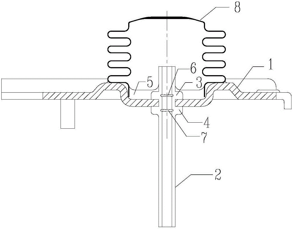
[0019] Such as figure 1 As shown, a thermostat base in the prior art includes a base plate 1 and a capillary tube 2, the upper surface of the base plate 1 is concave, the lower surface of the base plate 1 is convex, and a bellows 8 is soldered on the concave surface of the base plate, and the capillary tube 2 passes through Pass through the center of the bottom plate 1; the central perforation of the bottom plate 1 is used to install the capillary 2, the capillary 2 has two steps, one upper step 3, one lower step 4, the upper step 3 is against the concave surface of the bottom plate, the lower step 4 is against the convex surface of the bottom plate, the upper step Set a layer of solder 5 at step 3, from figure 1 In , it can be seen that there are two deformation grooves, namely the deformation groove 6 on the inner wall of the upper step and the deformation groove 7 on the inner wall of the lower step, both of which are riveted capillaries, and the inner wall performance afte...

Embodiment 2

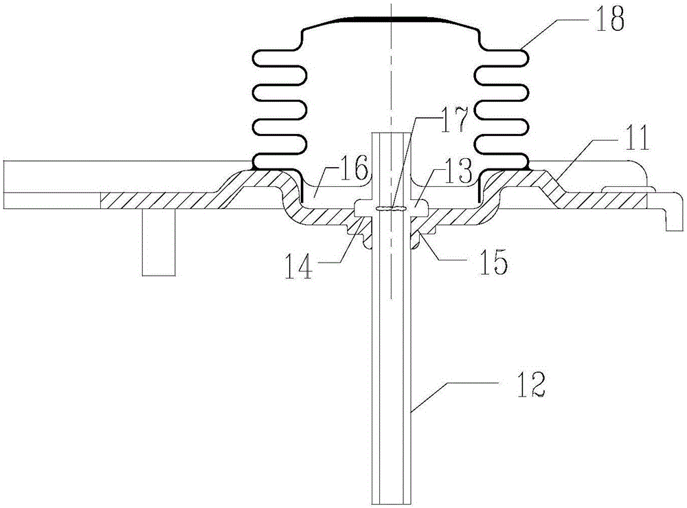
[0021] Such as figure 2 As shown, the present invention provides a thermostat base, including a base plate 11 and a capillary tube 12. The upper surface of the base plate 11 is concave, the lower surface of the base plate 11 is convex, and a bellows 18 is soldered on the concave surface of the base plate, and the capillary tube 12 passes through the base plate. Center; the central perforation position of the bottom plate 11 is used to install the capillary 12, a circular concave platform 14 is set in the center of the concave surface of the bottom plate 11, and an edge clamping structure 15 is set in the center of the convex surface of the bottom plate 11, and the edge clamping structure 15 is superimposed by two convex platforms structure, used to clamp the capillary 12 passing through the bottom plate 11, the capillary 12 is provided with a step 13, the step 13 corresponds to the circular concave platform 14, and is installed in the circular concave platform 14, and the conc...


PUM


Abstract

The invention discloses a temperature controller pedestal and a manufacturing technique. The temperature controller pedestal comprises a base plate and a capillary tube. The upper surface of the base plate is a concave surface and the lower surface of the base plate is a convex surface; a corrugated pipe is welded to the concave surface of the base plate; and the capillary tube passes through the center of the base plate. The capillary tube is installed in a central through hole of the base plate; a circular recessed bench is arranged at the center of the concave surface of the base plate; and a side clamping structure being a structure formed by superposition of two bosses is formed at the center of the convex surface of the base plate and is used for clamping the capillary tube passing through the base plate. A step is arranged at the capillary tube, wherein the step corresponding to the circular recessed bench is installed in the circular recessed bench. According to the invention, on the basis of the changing design of the base plate and the capillary tube, the traditional design thinking as well as the existing phenomenon of usage of two steps in the existing product in the prior art are broken through. Because only one step is design, a phenomenon of deformation of the inner wall with two steps of the capillary tube in the prior art can be changed fundamentally, so that the leakage risk caused by riveting deformation can be directly eliminated.

Description

technical field [0001] The invention relates to a temperature controller base and a production process, belonging to the technical field of temperature controllers. Background technique [0002] In the existing technology, the leakage of the working fluid of the thermostat has always been the main reason for the failure of the thermostat market, and it is also the fatal defect of the thermostat products. At present, the riveting of the thermostat bottom plate is secondary riveting, such as figure 1 As shown, two steps are riveted up and down on the bottom plate for fixing. [0003] The fixed step is formed as the mold riveting the capillary to deform the copper tube. Due to the large deformation of the capillary, it is inevitable to produce small cracks and dislocation gaps; the upper step can effectively improve the sealing reliability after being soldered and covered; the lower step There is a certain risk of leakage in riveting deformation; at present, the riveting effec...

Claims


Application Information

Patent Timeline
IPC IPC(8): H01H37/04H01H37/38H01H11/00
CPCH01H11/00H01H37/04H01H37/38
Inventor 戴相国
Owner 江苏汇商电器有限公司
Why Eureka
Try Eureka