Method for supporting portable terminal

A portable terminal and terminal technology, applied in the direction of casing/cabinet/drawer components, etc., can solve the problems of poor stability, easy loss, stability check, etc., and achieve the effect of easy implementation, simple structure and good stability

Inactive Publication Date: 2015-12-02
长沙蓝锐知识产权咨询有限公司
View PDF5 Cites 0 Cited by
  • Summary
  • Abstract
  • Description
  • Claims
  • Application Information

AI Technical Summary

Problems solved by technology

With the advancement of technology, the current portable terminals basically support video playback. However, the existing portable terminals generally do not have an oblique support mechanism. User fatigue and poor stabilit

Method used


Image

  • Method for supporting portable terminal
  • Method for supporting portable terminal
  • Method for supporting portable terminal

Examples


Embodiment 1

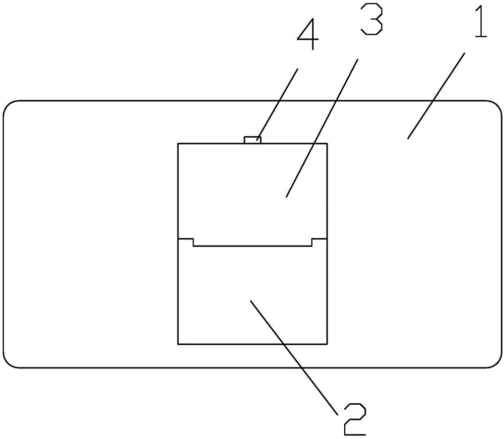
[0035] Such as Figure 1-2 As shown, a method for supporting a portable terminal is provided with a recessed part 6 and a folding plate support mechanism on the back of the terminal body; the recessed part is a square recessed part;

[0036] The flap support mechanism includes a lower flap and a lower flap hinged to each other; the lower side of the lower flap is hinged to the lower side of the recessed portion, and the lower flap can be turned outward relative to the lower side of the recessed portion;

[0037] When the terminal body does not need to be supported, the folding plate supporting mechanism is in the recessed part;

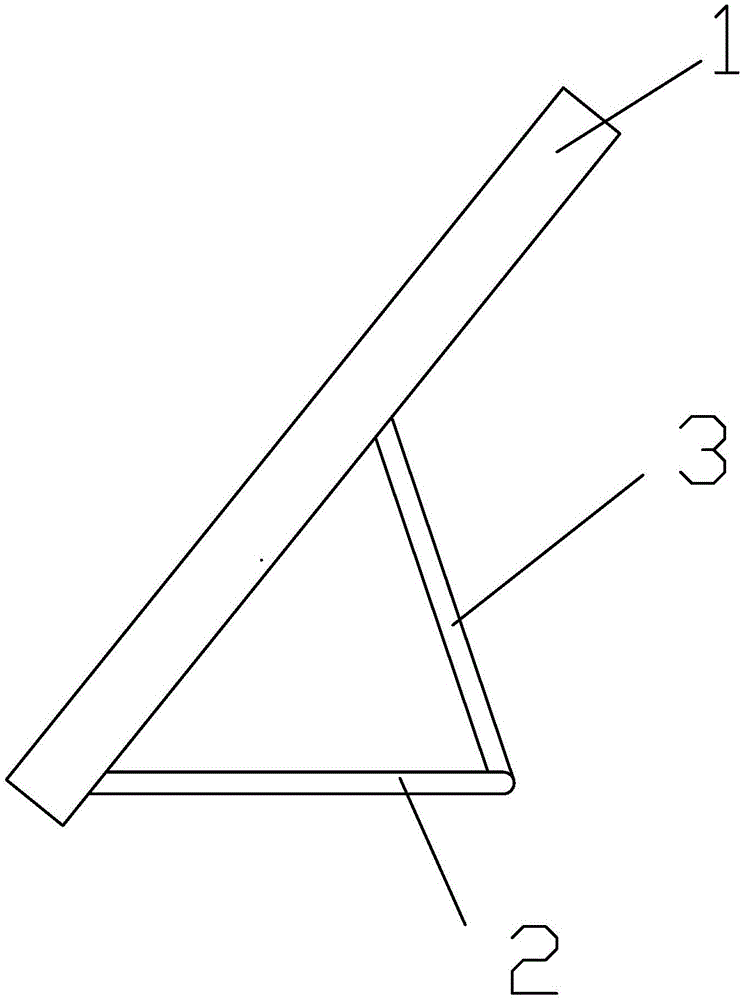
[0038] When the terminal body needs to be supported, the lower flap in the flap support mechanism is placed flat, while the upper flap is folded back towards the terminal body, and the upper side of the upper flap is pushed against the upper side plate of the concave part to complete the flap support The mechanism supports the terminal body.

[0039...

Embodiment 2

[0040] Example 2, such as Figure 1-5 As shown, a method for supporting a portable terminal is provided with a recessed part 6 and a folding plate support mechanism on the back of the terminal body; the recessed part is a square recessed part;

[0041] The flap support mechanism includes a lower flap and a lower flap hinged to each other; the lower side of the lower flap is hinged to the lower side of the recessed portion, and the lower flap can be turned outward relative to the lower side of the recessed portion;

[0042] When the terminal body does not need to be supported, the folding plate supporting mechanism is in the recessed part;

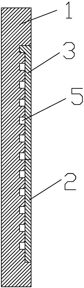
[0043] When the terminal body does not need to be supported, the top of the upper flap is fastened with the back of the terminal body through buckles 4 .

[0044] The bottom surface of the concave part is provided with 11 transverse grooves 5; the grooves are parallel to each other; the grooves are used to accommodate the top of the upper ...


PUM


Abstract

The invention provides a method for supporting a portable terminal. The backside of a terminal body is provided with a recessed portion (6) and a folding plate supporting mechanism, the recessed portion is a square recessed portion, the folding plate supporting mechanism comprises an upper folding plate and a lower folding plate hinged to each other, the lower side of the lower folding plate is hinged to the lower side portion of the recessed portion, and the lower folding plate can turn outwardly relative to the lower side portion of the recessed portion; when the terminal body does not need a support, the folding plate supporting mechanism is positioned in the recessed portion; when the terminal body needs the support, the lower folding plate of the folding plate supporting mechanism is arranged in a flat manner, the upper folding plate folds reversely towards the direction of the terminal body, the upper side of the upper folding plate is arranged in the recessed portion, and the support of the folding plate supporting mechanism for the terminal body is accomplished; and when the terminal body does not need the support, the top of the upper folding plate and the backside of the terminal body are buckled via a buckle (4). According to the method for supporting the portable terminal, the structure of an inclined support mechanism is simple, the conception is ingenious, and the support is stable.

Description

technical field [0001] The present invention relates to a method for supporting a portable terminal. Background technique [0002] Portable terminals mainly include mobile phones, mp4 players, PDAs and tablet computers. With the advancement of technology, the current portable terminals basically support video playback. However, the existing portable terminals generally do not have an oblique support mechanism. User fatigue and poor stability bring inconvenience. Another portable terminal uses a pull-out pole to form a diagonal support. This support method is a point support, which checks the stability, and the pole and the terminal are separated. , easily lost. Therefore, it is necessary to provide a method for supporting a portable terminal that is convenient to use and has good stability. Contents of the invention [0003] The technical problem to be solved by the present invention is to provide a method for supporting a portable terminal. The oblique support mechanis...

Claims


Application Information

Patent Timeline
IPC IPC(8): H05K5/02
Inventor 程文云
Owner 长沙蓝锐知识产权咨询有限公司
Why Eureka
Try Eureka