Electronic torque wrench

An electronic unit and torque measurement technology, which can be used in surgery, surgical lighting, medical science, etc., can solve the problem of not being able to protect the electronic components inside the wrench

Active Publication Date: 2015-12-02
GAUTHIER BIOMEDICAL
View PDF17 Cites 5 Cited by
  • Summary
  • Abstract
  • Description
  • Claims
  • Application Information

AI Technical Summary

Problems solved by technology

As such, the ability of prior art electronic torque wrenches to be cleaned to a sterile level is not a requirement for the construction of the electronic torque wrench, and accordingly, the design and construction of these prior art wrenches fails to protect the internal electronic components of these types of wrenches to Enables electronic torque wrenches to be used in environments where the wrench needs to be sanitized prior to use

Method used


Image

  • Electronic torque wrench
  • Electronic torque wrench
  • Electronic torque wrench

Examples


Embodiment Construction

[0102] Reference will now be made in detail to various embodiments of the present invention, one or more examples of which are illustrated in the accompanying drawings. Each example is provided by way of illustration of the invention and not by way of limitation. In fact, it will be apparent to those skilled in the art that modifications and variations can be made in the present invention without departing from the scope and spirit of the invention. For example, features shown or described as part of one embodiment can be used on another embodiment to yield still other embodiments. Accordingly, the present invention is intended to include such modifications and variations as fall within the scope of the appended claims and their equivalents.

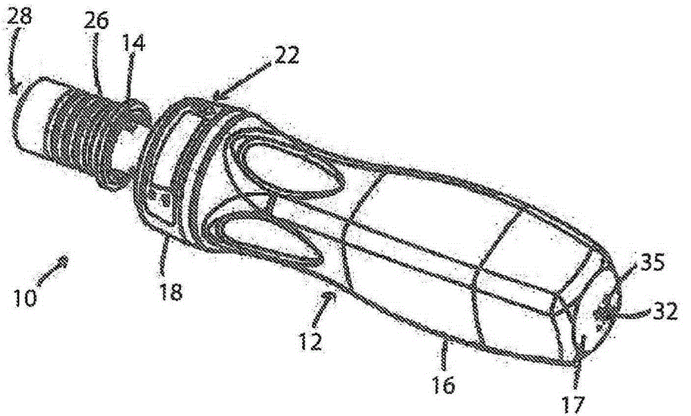
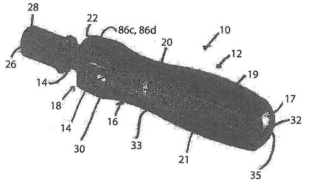
[0103] see now figure 1 and figure 2 , an inline electronic torque wrench 10 according to the present invention is shown. The electronic torque wrench 10 includes a wrench body 12 , a ratchet / wrench shaft 14 , a resilient grip 16 , ...


PUM


Abstract

A torque wrench for use in driving fasteners is provided. The wrench includes an electronics unit disposed within a housing engaged with the body of the wrench that is capable of sensing and measuring the torque applied to a fastener by the wrench and providing an output of the level of torque to the user. The data sensed by the electronics unit can be utilized to provide feedback to the user regarding the operation of the wrench, and to monitor the overall operation of the wrench for calibration purposes, among other functions. During use, the wrench can provide the user with visual, audible and tactile feedback regarding the operation of the device relative to stored maximum torque values stored in the electronics unit. The housing f or the electronics unit can be formed to be a single use component of the tool or can be designed for multiple uses with a configuration that can be engaged with cradles forming the body of the wrench having various different configurations.

Description

[0001] Cross references to related patent applications [0002] This application is a continuation-in-part of U.S. nonprovisional patent application serial number 13 / 915,395, filed June 11, 2013, which is a continuation-in-part of U.S. nonprovisional patent application serial number, filed May 18, 2011 13 / 110,446 (now U.S. Patent No. 8,485,075), which in turn claims priority to U.S. Provisional Patent Application Serial No. 61 / 345,817, filed May 18, 2010, and which also claims to be filed at Priority of U.S. Provisional Patent Application Serial No. 61 / 729,918, filed November 26, 2012, and U.S. Provisional Patent Application Serial No. 61 / 784,396, filed March 14, 2013, which are expressly incorporated by reference in their entirety into this article. technical field [0003] The present invention relates to tools, and more particularly to tools including electronic measurement and display means for indicating the force exerted by the tool. Background technique [0004] Typ...

Claims


Application Information

Patent Timeline
Patent Type & Authority Applications(China)
IPC IPC(8): A61B17/88
CPCA61B17/8875A61B19/5202A61B2019/466A61B2019/4868A61B90/30A61B2090/066A61B2090/0813
Inventor M·T·高蒂尔A·R·S·布拉甘扎D·约特S·A·高蒂尔
Owner GAUTHIER BIOMEDICAL
Why Eureka
Try Eureka