Pilot-operated safety valve with split structure of the lower disc of the pilot valve
What is Al technical title?
Al technical title is built by PatSnap Al team. It summarizes the technical point description of the patent document.
A technology of pilot-operated safety valve and split structure, which is applied in safety valves, balance valves, valve devices, etc. It can solve problems such as difficult to form pulse pressure, valve failure, and poor exhaust of pilot valves, so as to reduce motion friction, Improved sealing performance and good pulse effect
Active Publication Date: 2017-11-17
KAIFENG RUIFA HIGH & MIDDLE PRESSURE VALVE
View PDF7 Cites 1 Cited by
Summary
Abstract
Description
Claims
Application Information
AI Technical Summary
This helps you quickly interpret patents by identifying the three key elements:
Problems solved by technology
Method used
Benefits of technology
Problems solved by technology
In the dynamic process of valve opening, discharging and reseating, the shaft of the lower disc is centered and guided in the seat of the pilot valve, and the disc of the lower disc needs to be sealed. The assembly accuracy of related parts and its own precision are very high. The lower disc The shaft part and the lower disc disc must move synchronously; and the shaft part of the lower disc disc is often skewed and jammed when moving, resulting in the sealing of the lower disc disc, making it difficult to form pulse pressure, poor exhaust of the pilot valve, and failure of the main valve Unsmooth, action failure, valve failure, user feedback is relatively large, which seriously affects the social and economic benefits of valve manufacturers
Method used
Image
Click on the blue label to locate the original text in one second.
Reading with bidirectional positioning of images and text.
Examples
Embodiment Construction
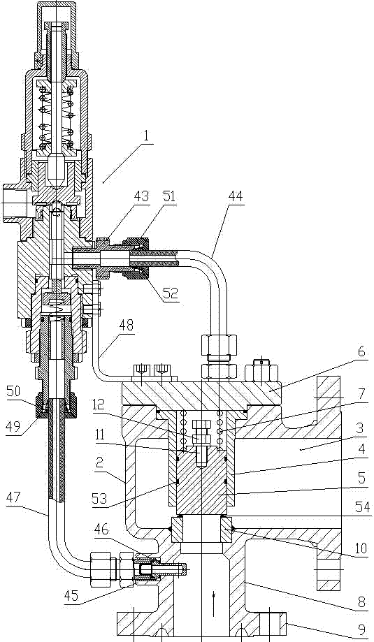
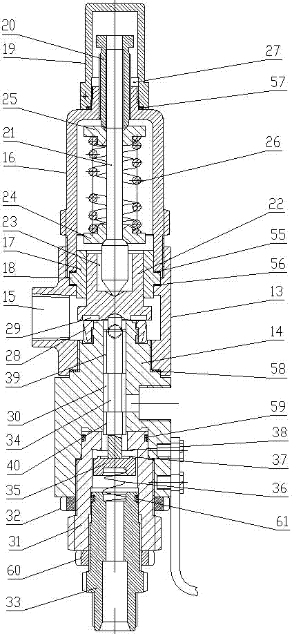
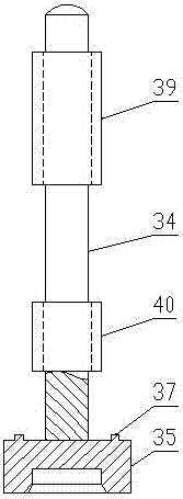
[0021] Such as Figure 1-Figure 4 As shown, the pilot safety valve of the present invention with the split structure of the lower disc of the pilot valve includes a main valve and a pilot valve 1 .
[0022]The main valve includes a main valve body 2 with a hollow structure. The side of the main valve body 2 is provided with a main pressure relief port 3 . It is equipped with a main valve guide sleeve 4 whose lower part extends into the main valve body 2. The main valve guide sleeve 4 is slidably connected with a main valve disc 5. The top of the main valve body 2 is provided with a main valve valve above the stepped hole. Cover 6, the main valve spring 7 is provided between the upper end of the main valve disc 5 and the lower surface of the main valve cover 6, and the main connecting pipe 8 coaxial with the step hole is provided at the lower end of the main valve body 2, and the main connecting pipe 8 The lower end is provided with a connecting flange 9, which is used to conn...
PUM
Abstract
The invention relates to a pilot valve lower valve clack split-structure pilot operated safety valve which comprises a main valve and a pilot valve, wherein the main valve comprises a main valve body, a guide sleeve, a main valve clack, a main valve cap, a main valve spring, a main connecting pipe, a main valve seat, a main valve limit screw and the like; and the pilot valve comprises a pilot valve body, a pilot valve seat, a pilot valve cap, a pilot valve guide sleeve, a seal locating ring, an upper valve cap, an adjusting bolt, a valve stem, a guide valve clack, a lower spring seat, an upper spring seat, an upper spring, a locking nut, a locating sleeve, an adjusting casing, a lower valve clack shaft, a lower valve clack disk, a lower spring, a lower seal ring, an upper seal ring, an upper guide post and a lower guide post. The pilot valve lower valve clack adopts the split structure, thereby enhancing the pulse effect and synchronization sensitivity of the pilot valve, and ensuring the various action properties and sealing reliability of the pilot operated safety valve. The pilot valve lower valve clack split-structure pilot operated safety valve is suitable for high-pressure high-discharge-capacity high-discharge-back-pressure working conditions in need of quick pressure relief.
Description
technical field [0001] The invention relates to a valve, in particular to a pilot-operated safety valve with a split structure of the lower disc of the pilot valve. Background technique [0002] Pilot-operated safety valve (also known as pulse safety valve) is composed of a main valve and a pilot valve, the main valve is a real safety valve, and the pilot valve is used to sense the pressure of the pressurized system and make the main valve open and close . The pilot-operated safety valve is designed using the principle of failure to open. [0003] The lower disc of the pilot valve of the existing pilot-operated safety valve is an integral structure. During the working process, the lower disc of the pilot valve slides up and down in the seat of the pilot valve to form a pulse pressure to control the opening, discharge and return of the pilot valve. Seat, which determines the action performance of the main valve. The upper part of the lower disc of the integral pilot valve ...
Claims
Application Information
Patent Timeline
Application Date:The date an application was filed.
Publication Date:The date a patent or application was officially published.
First Publication Date:The earliest publication date of a patent with the same application number.
Issue Date:Publication date of the patent grant document.
PCT Entry Date:The Entry date of PCT National Phase.
Estimated Expiry Date:The statutory expiry date of a patent right according to the Patent Law, and it is the longest term of protection that the patent right can achieve without the termination of the patent right due to other reasons(Term extension factor has been taken into account ).
Invalid Date:Actual expiry date is based on effective date or publication date of legal transaction data of invalid patent.