Telescopic monitoring vertical rod convenient to install

A technology that facilitates installation and monitoring of poles. It is used in color TV components, TV system components, and TV. It can solve the problems of intelligent monitoring equipment failing to achieve monitoring effects, high construction costs, and personalized installation. Achieve good monitoring effect, control cost, and meet installation requirements

Inactive Publication Date: 2015-12-09
CHENGDU ZHONGFU LIXIANG TECH
View PDF5 Cites 6 Cited by
  • Summary
  • Abstract
  • Description
  • Claims
  • Application Information

AI Technical Summary

Problems solved by technology

Since the mass-produced poles cannot be installed individually according to the terrain and other specific conditions, the intelligent monitoring equipment will not be able to achieve a good monitoring effect
Moreover, when installing or maintaining the pole of the intelligent monitoring equipment, it is necessary to use a crane to set up or put down the pole, and professional guidance is needed, so the construction cost is high

Method used


Image

  • Telescopic monitoring vertical rod convenient to install
  • Telescopic monitoring vertical rod convenient to install
  • Telescopic monitoring vertical rod convenient to install

Examples


Embodiment 1

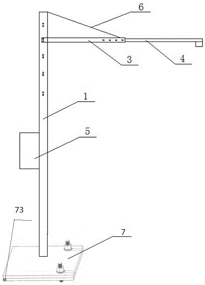
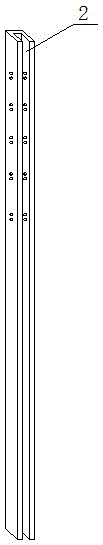
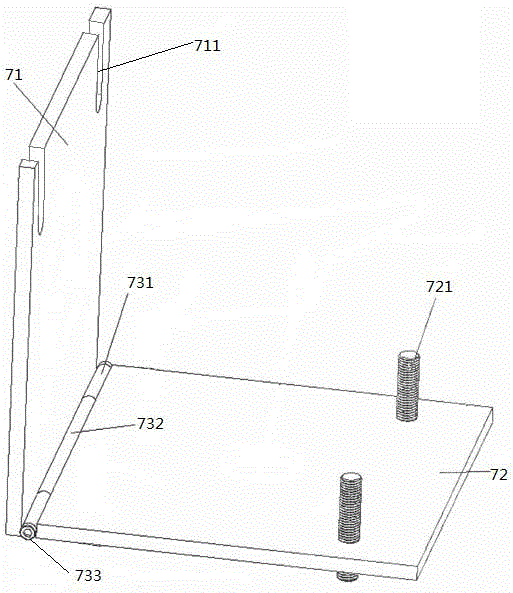
[0019] A telescopic monitoring pole that is convenient to install includes a pole body 1, a bracket, and a movable base 7. The pole body 1 is connected to the bracket. It is characterized in that there are at least two different heights on the pole body 1. Where the bracket is installed, the cross section of the pole body 1 is a groove structure. The support is connected to the pole body 1 by bolts, and the support is composed of at least two sub-supports fixedly connected, and there are at least two installation positions with different telescopic lengths between the sub-supports. The movable base 7 includes a panel 71 , a bottom plate 72 , and a movable sleeve device 73 , the panel 71 is movably connected up and down with the bottom plate 72 through the movable sleeve device 73 , and the panel 71 is fixedly connected with a pole body. The movable sleeve device 73 includes a panel 71 sets, a base plate 72 sets and a central rod 733, the panel 71 sets are fixedly installed on ...

Embodiment 2

[0022] On the basis of Embodiment 1, when installing the bracket, insert the bracket end into the groove structure 2, and then fix it with bolts. When it is necessary to adjust the height of the monitoring equipment, take out the fixing bolt in the positioning hole of the pole body 1, then move the bracket up and down, and insert the end of the bracket into the bolt hole position of a certain height in the groove structure 2, and the end of the bracket Align the positioning hole with the bolt installation hole 1 of the pole body, and then fix it with bolts. In this way, the height adjustment function of the monitoring pole is realized, and the height of the pole can be flexibly controlled according to different environments, so as to achieve the most ideal monitoring effect.

[0023] Described support is made up of front support 4 and rear support 3, and the rear end of described front support 4 is socketed with rear support 3, and is fixed by bolt between front support 4 and ...

Embodiment 3

[0025] On the basis of the above-mentioned embodiments, a box body 5 is provided on the pole body 1 , and the box body 5 is sleeved on the outside of the pole body 1 . Casing 5 is used for installing the control system of intelligent monitoring camera, and intelligent alarm system. A pull wire 6 is provided between the top of the pole body 1 and the rear bracket 3 . The pulling force of the stay wire 6 can reduce the moment of the bracket relative to the connection point of the pole body 1, thereby preventing the bracket from breaking. The length of the stay wire 6 can be adjusted according to the different installation positions of the bracket on the pole body 1 .


PUM


Abstract

The invention discloses a telescopic intelligent monitoring vertical rod convenient to install, and relates to the field of traffic facility manufacturing, in particular to a vertical rod for installing monitoring equipment. The vertical rod for installing the intelligent monitoring equipment is convenient to install and detach, and the installing height and telescopic distance of the vertical rod can be flexibly adjusted according to site conditions. According to the technical scheme, the intelligent telescopic monitoring vertical rod convenient to install comprises a vertical rod body, supports and a movable base. The vertical rod body and the supports are connected. At least two positions, for installing the supports, of different heights are arranged on the vertical rod body, and each support is formed by fixedly connecting at least two sub supports, wherein at least two installing positions of different telescopic lengths are arranged between the sub supports. The movable base comprises a panel, a bottom plate and a movable sleeve device, the panel is movably and vertically connected with the bottom plate through the movable sleeve device, and the panel is fixedly connected with the vertical rod body. The vertical rod is suitable for installing the intelligent monitoring equipment.

Description

Technical field [0001] The invention involves the field of transportation facilities, especially a vertical pole that installs monitoring equipment. Background technique [0002] Intelligent monitoring technology is the use of computer image visual analysis technology to analyze and track the goals in the camera airport by separating the background and goals in the scene.The user can analyze the module based on different illegal rules in the scenes of different cameras. Once the target has violated the pre -defined rules in the scene, the system will automatically issue an alarm information. The monitoring command platform will automatically pop up the alarm information information.And issuing warning sounds and triggering linkage related devices. Users can reorganize the alarm scene by clicking the alarm information and take relevant preventive measures.As the demand for intelligent monitoring equipment continues to increase, the demand for the vertical pole of the installation ...

Claims


Application Information

Patent Timeline
Patent Type & Authority Applications(China)
IPC IPC(8): F16M11/04F16M11/28H04N5/232
Inventor 汪海李国
Owner CHENGDU ZHONGFU LIXIANG TECH
Why Eureka
Try Eureka