
Radio-frequency power detection circuit

A detection circuit, radio frequency power technology, applied in the direction of measuring electrical variables, measuring electrical power, electrical devices, etc., can solve the problem of insufficient detection accuracy, achieve the effect of improving the detection accuracy of radio frequency power, improving detection accuracy, and flexible application

Active Publication Date: 2015-12-09
HUAZHONG UNIV OF SCI & TECH
View PDF6 Cites 15 Cited by
  • Summary
  • Abstract
  • Description
  • Claims
  • Application Information

AI Technical Summary

Problems solved by technology

[0007] The technical problem to be solved by the present invention is that the general radio frequency power detection technology based on the detection diode has the problem that the detection accuracy is not high enough in a certain frequency and power range

Method used


Image

  • Radio-frequency power detection circuit
  • Radio-frequency power detection circuit
  • Radio-frequency power detection circuit

Examples


Embodiment Construction

[0025] In order to make the objectives, technical solutions, and advantages of the present invention clearer, the following further describes the present invention in detail with reference to the accompanying drawings and embodiments. It should be understood that the specific embodiments described here are only used to explain the present invention, but not to limit the present invention.

[0026] Such as Figure 4 As shown in the principle diagram of the radio frequency peak power detection method of the present invention, in the radio frequency peak power detection circuit of the present invention, the signal flow is:

[0027] 1. After the signal to be measured passes through the load matching unit, it enters the peak detection unit;

[0028] 2. The output of the peak detection unit is compensated by the peak compensation unit;

[0029] 3. The output of the peak compensation unit is used as the two inputs of the multiplier unit to realize multiplication;

[0030] 4. The output signal...


PUM


Abstract

The invention discloses a radio-frequency power detection circuit. According to the invention, a radio-frequency input signal is connected to a matching load and processed via a peak detection circuit based on a wave detecting diode; the output of the peak detection circuit is connected to a peak compensation circuit so that the compensated direct-current level is basically consistent with the radio-frequency signal peak; the output of a compensation circuit is connected to two input ends of a multiplying unit; and after filtering, amplification and zero compensation are performed on the output of the multiplying unit, a direct current signal in direct proportion to the power of a to-be-detected signal is obtained on the output end of the detection circuit. The power detection circuit is characterized in that all functional circuits are mutually independent and convenient to debug; the compensation circuit can be precisely adjusted and measurement precision degree is quite high in a certain frequency and power range; by setting circuit parameters, responding speed is flexible and adjustable; and over hundreds of milliwatt of radio-frequency signal power can be measured, and the power detection circuit has quite high practical value and attractive application prospect.

Description

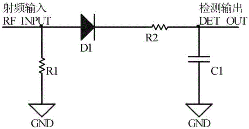
Technical field [0001] The invention relates to low radio frequency power detection in the intermediate to very high frequency bands in the field of accelerators and radio frequency ion sources, and more specifically, to a low radio frequency power detection circuit based on a detection diode. Background technique [0002] Radio frequency refers to electromagnetic frequencies that can be radiated into space. The frequency range covered by intermediate frequency to very high frequency is 300kHz~300MHz. At present, the main techniques used in low radio frequency power detection in this frequency band are as follows: [0003] 1. Use high-speed diodes as detectors to detect RF signal power, such as figure 1 As shown, after the input signal is detected by the diode, the envelope of the radio frequency signal is output. In practice, the diode cannot work in an ideal state, that is, when the input waveform is in the negative half cycle, the diode cannot be completely turned off; and durin...

Claims


Application Information

Patent Timeline
Patent Type & Authority Applications(China)
IPC IPC(8): G01R21/00
Inventor 李冬王弘毅秦斌陈德智刘开锋王晓敏赵鹏
Owner HUAZHONG UNIV OF SCI & TECH
Learn More