
Method and preheating control apparatus of compressor

A preheating control and compressor technology, applied in engine control, AC motor control, pump control, etc., can solve problems such as compressor temperature error, difficulty in performing compressor preheating control, and inability to correctly estimate motor coil resistance, etc., to achieve Effects of eliminating voltage errors and improving accuracy

Inactive Publication Date: 2010-01-13
SAMSUNG ELECTRONICS CO LTD
View PDF6 Cites 0 Cited by
  • Summary
  • Abstract
  • Description
  • Claims
  • Application Information

AI Technical Summary

Problems solved by technology

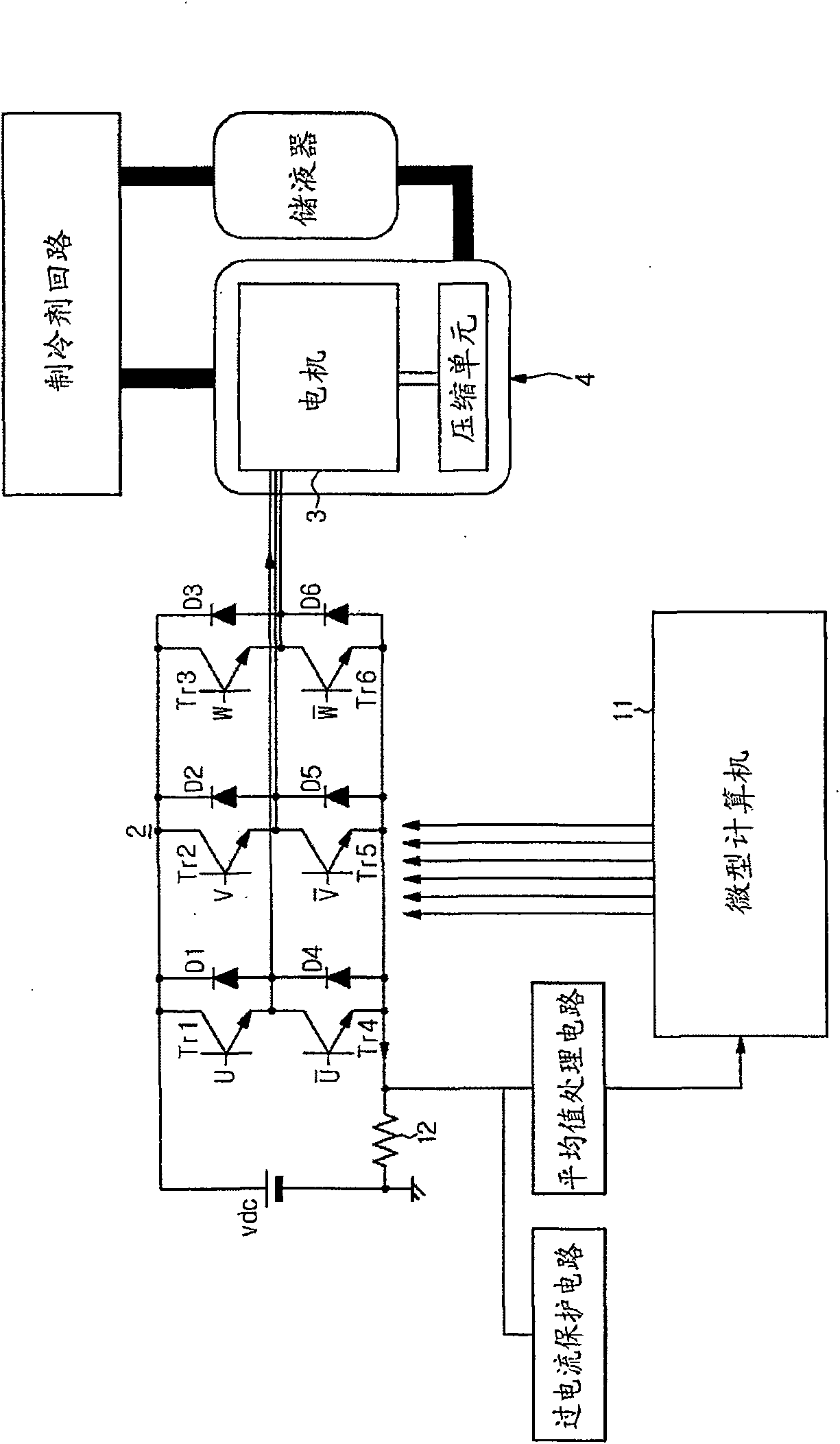
[0006] Therefore, among the six switching elements (Tr1 to Tr6) constituting the inverter 2, only two switching elements conduct current, which causes the deterioration of the switching elements due to current switching to be concentrated on the two switching elements. Of the three-phase coils, current is supplied only to the two-phase coils, so it is difficult to uniformly preheat the compressor using the heat generated by copper loss, and the deterioration of the motor coils is also concentrated on the two-phase coils
[0007] When the two-phase energization method is used in this way, due to the nonlinear characteristics of the switching elements constituting the inverter 2 (for example, the on / off (off) of the switching elements is delayed), it is necessary to rely solely on the switching elements The on-off ratio and the way of the inverter DC voltage cannot correctly calculate the voltage switched on to the motor
[0008] That is, since the voltage applied to the motor cannot be correctly calculated, the coil resistance of the motor cannot be correctly estimated, which in turn causes an error in the calculated internal temperature of the compressor, making it difficult to perform correct compressor warm-up control

Method used


Image

  • Method and preheating control apparatus of compressor
  • Method and preheating control apparatus of compressor
  • Method and preheating control apparatus of compressor

Examples


Embodiment Construction

[0021] Hereinafter, preferred embodiments of the present invention will be described in detail with reference to the accompanying drawings.

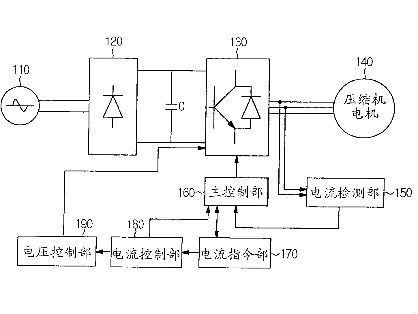
[0022] figure 2 It is a structural diagram of the drive system of the compressor motor provided according to the embodiment of the present invention. The rectifier unit 120, the inverter 130, the compressor motor 140, the current detection unit 150, the main control unit 160, the current command unit 170, and the current control unit The unit 180 and the voltage control unit 190 are constituted.

[0023] The rectifier 120 rectifies the alternating current (AC) power source 110 to generate a direct current power source, and the rectified direct current power source is smoothed by a capacitor (C) to supply a direct current (DC) power source.

[0024] The inverter 130 converts the DC power supplied by the rectifier unit 120 into a three-phase AC power (U, V, W) in the form of pulses having an arbitrary variable frequency and supplies it t...


PUM


Abstract

The invention relates to a device and method for the compressor preheating control. Specifically speaking, the invention detect the internal temperature of the compressor without the detecting unit for the special monitoring compressor internal temperature; the invention adjusts the compressor coil and the heating time according to the detected internal temperature of the compressor; so that the electric engine stator coil installed in the compressor uses the lost heat after connecting the current. The tri-phase inverter compressor preheating device provided by the invention comprises a current instruction potion for periodically changing the instruction current according to the predetermined instruction current pattern; a current control potion for generating the instruction voltage fro tracking the instruction current; a main control potion for calculating the internal temperature of the compressor according to the instruction current of at least two phases and the instruction voltage after sampling the instruction current and the instruction voltage, and controlling preheating according to the calculating temperature.

Description

technical field [0001] The invention relates to a compressor preheating control device and method, in particular, to detecting the internal temperature of the compressor without using a detection unit specially monitoring the internal temperature of the compressor, and adjusting the compressor coil according to the detected internal temperature of the compressor A compressor preheating control device and method for preheating the compressor by using the heat lost by the coil after the current is turned on to the motor stator coil installed inside the compressor. Background technique [0002] Generally, if the compressor is started in a state where a large amount of liquid refrigerant is dissolved in the compressor lubricating oil (ie, when the temperature outside the air conditioner outdoor unit is low), the compressor may be damaged. In order to prevent this phenomenon, when the external temperature of the compressor is low, the commonly used method is to use a special comp...

Claims


Application Information

Patent Timeline
Patent Type & Authority Patents(China)
IPC IPC(8): H02P27/06F24F11/02
CPCF04B35/04F04B49/06F05B2210/12F05B2260/60F05B2270/303Y10S417/00
Inventor 李光云李濬焕
Owner SAMSUNG ELECTRONICS CO LTD
Learn More