
Automobile dynamic display method and high-position braking lamp system based on automobile dynamic display method

A high-position brake light and dynamic display technology, applied in the field of traffic safety, can solve the problems of incomplete brake light system filtering, inability to visually display vehicles, inaccurate signal flickering, etc., to avoid the threat of traffic accidents, facilitate intuitive observation, and design Humanized effect

Inactive Publication Date: 2015-12-16
刘东昌
View PDF7 Cites 5 Cited by
  • Summary
  • Abstract
  • Description
  • Claims
  • Application Information

AI Technical Summary

Problems solved by technology

[0007] In the prior art, technologies related to high-mounted brake lights have been studied. For example, in the patent 201310276168.0, the patent of automobile high-mounted brake lights, the high-mounted lights are designed into two groups, one set of brake light bars, and one set of warning light bars , it is only used to indicate whether the brake is on, so as to complete the alarm function, but this brake light can only be used to show whether the vehicle is braking, and cannot accurately express the intention of the people inside the vehicle, that is, whether the brake is an emergency brake , whether the braking ends during the process of releasing the brake pedal, whether the braking starts during the process of stepping on the brake pedal, etc. At the same time, it is impossible to visually show whether the vehicle is accelerating, resulting in the driver's intention and the vehicle's dynamics. Passing on to other traffic participants, subsequent traffic participants cannot make more reasonable judgments in advance to reduce traffic accidents; at the same time, the author found that the actual production of this patented technology relies on the speed sensor when it is used, and it is based on speed changes. Alarm, that is to say, if you brake suddenly at high speed, the warning light bar will not light up until the speed drops, so there will be a time difference, and traffic accidents will still occur within this time difference. The brake light system produced by the programmable controller has incomplete filtering, inaccurate signal flickering, and inconvenient installation due to the large structure; moreover, there is no dynamic display of the light group for the acceleration status of the car, and the display is incomplete. The existing high-mounted brake light sets are produced and installed according to the standards defined by the automobile manufacturers, resulting in the inconsistency of the high-mounted brake light sets of vehicles, causing difficulties in visual identification for traffic participants; with the development of society, the The growth and newly added drivers have caused extremely complex road conditions for traffic road driving
The function of the existing high-mounted brake light group of automobiles is too simple and single, and can no longer adapt to the existing complex traffic conditions

Method used


Image

  • Automobile dynamic display method and high-position braking lamp system based on automobile dynamic display method
  • Automobile dynamic display method and high-position braking lamp system based on automobile dynamic display method
  • Automobile dynamic display method and high-position braking lamp system based on automobile dynamic display method

Examples


specific example

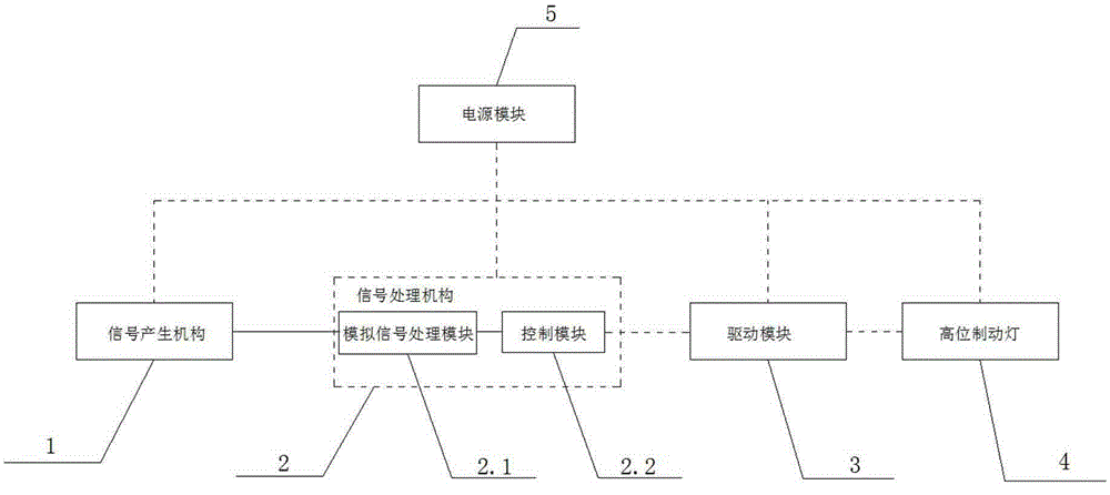
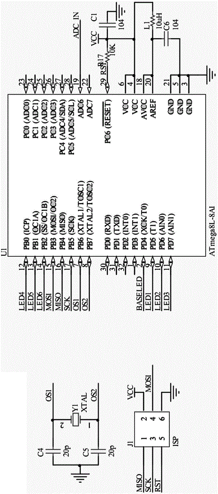
[0092] In the power module 5, the model of the voltage regulator chip is 78L05; the model of the ADC chip is ATmega8L-8AI, the ADC chip is an 8-way 10-bit ADC input, and contains 2KB of EEPROM to save parameters, and its maximum execution frequency is up to 16MHz, single-cycle instruction execution, cost-effective. Using an external crystal oscillator, the LC filter composed of L1 and C6 provides a stable power reference for the ADC conversion chip and supports online ISP programming.

[0093] The drive module 3 is driven by a high-power Darlington tube of the model ULN2003, and each channel can provide a maximum current of 500mA to ensure the normal and reliable operation of the LED.

[0094] The high-mount brake light 4 uses four basic lamp groups BASELED and six gradient lamp groups CHANGELED, and the current of each LED supports <=120mA.

[0095] Then adjust the pressure value corresponding to the highest voltage and the lowest voltage according to the pressure sensor sig...


PUM


Abstract

The invention discloses an automobile dynamic display method and a high-position braking lamp system based on the automobile dynamic display method. The automobile dynamic display method comprises the following steps: after a pedal is trod, pressure applied to the pedal generates a certain pressure signal, and the pressure signal is transmitted to a signal processing device; the signal processing device transforms the pressure signal into a current signal and controls a high-position braking lamp of an automobile to perform corresponding display. The pedal comprises a braking pedal and an accelerator pedal, the system structurally comprises a signal generating mechanism, a signal processing mechanism, the high-position braking lamp and a power supply module. Compared with the prior art, according to the automobile dynamic display method and the high-position braking lamp system based on the automobile dynamic display method, the operational intention of a driver in a front automobile can be displayed according to change conditions of the braking lamp, so that a subsequent traffic participant conveniently does reasonable judgments; the state display is comprehensive, states such as acceleration, deceleration, cruise, braking and emergency breaking of the automobile are displayed, so that the subsequent traffic participant conveniently observes the states in an audio-visual manner; the automobile dynamic display method and the high-position braking lamp system are good in practicality, humanized in design and easy to popularize.

Description

technical field [0001] The invention relates to the technical field of traffic safety, in particular to a highly practical and dynamic display method for automobiles and a high-position brake light system based on the method. Background technique [0002] High-mounted brake lights, also known as high-mounted brake lights, are auxiliary lights for brake lights. They are generally installed on the center line of the rear end of the vehicle, and some are installed on the upper end of the rear end of the vehicle. The current high-mounted brake lights are basically made of LEDs. The functions of high-mounted brake lights in driving generally include: [0003] (1) For the driver approaching the following vehicle, even if he does not see the brake light of the vehicle ahead, he can still see the signal of the high-mounted brake light; [0004] (2) When the vehicle in front is a passenger car, even if the brake light of the vehicle driving ahead is invisible, the running informatio...

Claims


Application Information

Patent Timeline
IPC IPC(8): B60Q1/54B60Q1/44B60Q1/50
Inventor 刘东昌
Owner 刘东昌
Learn More