RFID-based member relative displacement detection method

A technology of relative displacement and detection method, which is applied in the direction of computer parts, cooperative devices, instruments, etc., which can solve the problem of being easily affected by light, vibration, stains, etc., and the anti-loosening marks are easily covered by dust, oil, etc., and the technical difficulty is large. and other problems, to achieve the effect of small size, fast recognition speed and wide recognition range

Inactive Publication Date: 2015-12-16
ZHUZHOU CSR TIMES ELECTRIC CO LTD
View PDF5 Cites 11 Cited by
  • Summary
  • Abstract
  • Description
  • Claims
  • Application Information

AI Technical Summary

Problems solved by technology

Manual identification of loose mark detection method has the disadvantages of high labor intensity, and the anti-loose mark is easily covered by dust and oil; the image detection method uses image recognition technology to identify whether the fastener is loose, but its technology is difficult and costly. Affected by light, vibration, stains, etc., the rate of false positives and false negatives is high

Method used


Image

  • RFID-based member relative displacement detection method
  • RFID-based member relative displacement detection method
  • RFID-based member relative displacement detection method

Examples


Embodiment Construction

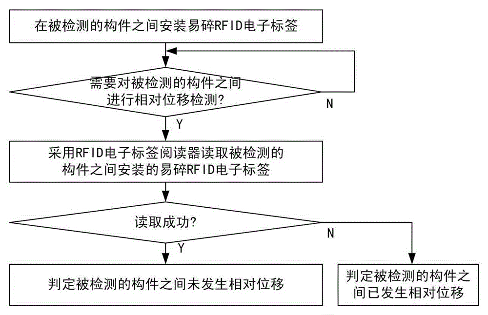
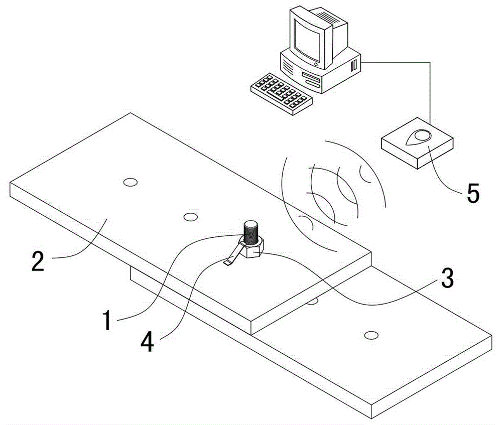
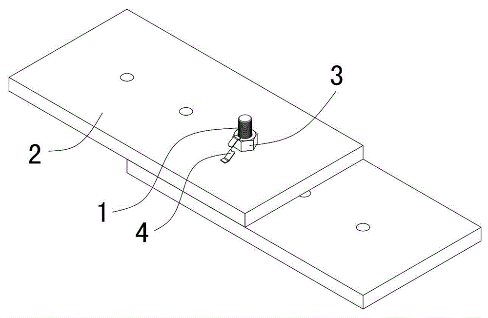
[0033] Hereinafter, taking the nut 3 of the bolt 1 and the installation base 2 of the bolt 1 as the components to be detected, and realizing the relative displacement detection between the nut 3 of the bolt 1 and the installation base 2 of the bolt 1 as an example, the RFID-based components of the present invention The relative displacement detection method is further described in detail.

[0034] Such as figure 1 As shown, the steps of the RFID-based component relative displacement detection method in this embodiment include:

[0035] 1) Install fragile RFID electronic tags between the components to be detected in advance, so that the fragile RFID electronic tags are respectively connected and fixed with the components to be detected; see figure 2 , the bolt 1 is installed on the installation base 2, and the upper side of the bolt 1 is provided with a nut 3 that is threaded. The connection is fixed.

[0036] 2) When it is necessary to detect the relative displacement betw...


PUM


Abstract

The invention discloses an RFID-based member relative displacement detection method. The steps include: 1) installing a fragile RFID electronic label in advance between members to be detected, and the fragile RFID electronic label being connected and fixed to the members to be detected; 2) when detection of relatively displacement of the members to be detected is needed, adopting an RFID electronic label reader to read the fragile RFID electronic label installed between the members to be detected, if the fragile RFID electronic label is read successfully, judging that no relative displacement occurs between the members to be detected, and otherwise judging that relative displacement occurs between the members to be detected. The RFID-based member relative displacement detection method provided by the invention has the advantages of fast identification speed, wide identification range, easy control, simplicity and practicability, small equipment size and flexible shape, convenient updating of data format, penetrability and barrier-free detection, good safety and wide range of application.

Description

technical field [0001] The invention relates to a technology for detecting relative displacement of mechanical components, in particular to a method for detecting relative displacement of components based on RFID. Background technique [0002] Relative displacement detection between two adjacent or connected components is a common detection requirement in daily applications. For example, in the field of locomotives, it is possible to judge whether two components have moved abnormally by detecting whether there is displacement between the two components, and it is also possible to determine whether one component is separated or lost relative to the other; in addition, it can also be used in building safety assessments. Whether two objects in buildings such as houses and bridges are displaced to determine whether the building components are damaged or whether the damage has expanded. The current commonly used method for this type of inspection is to manually measure the dista...

Claims


Application Information

Patent Timeline
Patent Type & Authority Applications(China)
IPC IPC(8): G06K17/00
Inventor 王俊平贺文施蔚加张小珍童磊尤勇阳帆沈云波凌志辉赵科龙王俊峰胡秋平言珊李萍
Owner ZHUZHOU CSR TIMES ELECTRIC CO LTD
Why Eureka
Try Eureka