Rotating electrical machine

A technology for rotating electric machines and wire groups, applied to the shape/style/structure of winding conductors, which can solve problems such as increased winding resistance, longer wire length, and lower efficiency

Inactive Publication Date: 2015-12-16
MITSUBISHI ELECTRIC CORP
View PDF4 Cites 0 Cited by
  • Summary
  • Abstract
  • Description
  • Claims
  • Application Information

AI Technical Summary

Problems solved by technology

Distributed winding has the advantage of reducing torque ripple and noise. On the other hand, since the height of the coil end becomes higher, the length of

Method used


Image

  • Rotating electrical machine
  • Rotating electrical machine
  • Rotating electrical machine

Examples


Embodiment approach 1

[0056] The rotating electrical machine 1 according to Embodiment 1 will be described.

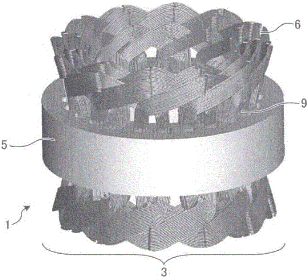
[0057] The rotating electrical machine 1 has a stator and a rotor. The rotor rotates relative to the stator, and the rotational power is transmitted to a mechanical device (not shown) via a shaft (not shown) fixed to the rotor to operate the mechanical device. The rotating electrical machine 1 is, for example, a permanent magnet type rotating electrical machine or an induction type rotating electrical machine. In the rotary electric machine 1, for example, the winding configuration in the stator 3 has been improved.

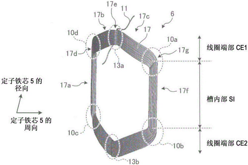
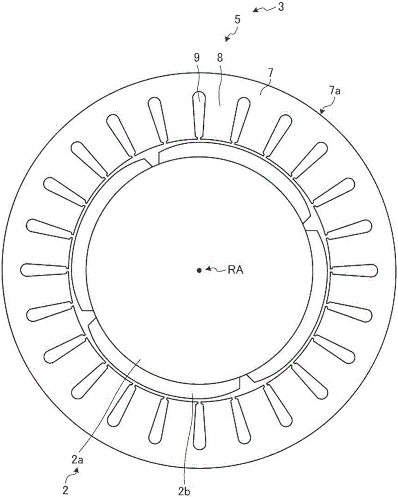
[0058] Specifically, the rotating electrical machine 1 has Figure 1 ~ Figure 3 structure shown. figure 1 It is a perspective view showing the configuration of a stator core and a stator winding in the rotating electric machine 1 . figure 2 It is a perspective view showing the structure of the coil in a stator winding. image 3 It is a figure which shows the structure at ...

Embodiment approach 2

[0132] Hereinafter, rotating electrical machine 200 according to Embodiment 2 will be described. Hereinafter, the description will focus on the differences from Embodiment 1. FIG.

[0133] In Embodiment 1, a coil is exemplarily described in which the conductive wires 11 arranged in two layers in the radial direction in the slot interior SI are changed to one layer in the radial direction at the coil ends CE1 and CE2. In Embodiment 2, a coil is exemplarily described in which the conductive wires 21 arranged in three layers in the radial direction in the slot interior SI are changed to one layer in the radial direction at the coil ends CE1 and CE2.

[0134] Specifically, in the stator winding 206 of the stator 203 of the rotary electric machine 200, as Figure 9 ~ Figure 11 As shown, the structure of each coil 217 forming the winding of each phase is different from Embodiment 1 in the following points. Figure 9 It is a figure which looked at the state which inserted the coil ...

Embodiment approach 3

[0156] Hereinafter, rotating electric machine 300 according to Embodiment 3 will be described. Hereinafter, description will focus on parts different from those in Embodiment 2. FIG.

[0157] In Embodiment 2, the coil 217 is exemplarily described in which the arrangement of the conducting wires 21 in three layers in the slot interior SI is changed to one layer in the coil ends CE1 and CE2, but as seen Figure 13 It can also be seen that the conductive wires 21 at the coil ends CE1 and CE2 pass through the area corresponding to the first layer or the third layer inside the slot SI, and the area corresponding to the second layer inside the slot is not used at the coil ends.

[0158] Therefore, in Embodiment 3, the method of making a conducting wire also pass through the area|region corresponding to the 2nd layer of the slot interior SI in coil end part CE1, CE2 is demonstrated.

[0159] Specifically, in the stator winding 306 of the stator 303 of the rotary electric machine 300...


PUM


Abstract

Each of one or more coils in a rotating electrical machine comprises: a first m-stage (m is an integer of two or more) conductor line group arranged in the radial direction of a stator core in a slot; a second conductor line group formed by changing the arrangement of the first conductor line group to n stages (n is an integer of one or more) in the radial direction of the stator core at a coil end; a first bent portion where the first conductor line group and the second conductor line group are bent to form an angle (theta) smaller than 180 DEG at the boundary between the inside of the slot and the coil end; a third conductor line group formed by changing the arrangement of the second conductor line group arranged from first through nth stages in the radial direction of the stator core at the coil end into (m - n + 1)th through mth stage in the radial direction of the stator core; and a second bent portion where the second conductor line group and the third conductor line group are bent to form an angle (theta ') smaller than 180 DEG at the coil end. Wherein, the numbers (m, n) of stages satisfy n/m <=1/2.

Description

technical field [0001] The invention relates to a rotating electric machine. Background technique [0002] Currently, against the background of the influence of rising resource prices and the movement to prevent the global warming of the earth, the awareness of reducing the amount of energy used as a source of carbon dioxide generation is increasing. Among them, rotating electrical machines, which consume about 40% of the world's total power generation, have attracted attention, and improvement of their efficiency has become a top priority. [0003] Stator windings of rotating electrical machines are roughly classified into concentrated winding and distributed winding. Distributed winding has the advantage of reducing torque fluctuations and noise. On the other hand, since the height of the coil end becomes higher, the length of the wire becomes longer, which has the disadvantages of an increase in winding resistance, that is, an increase in copper loss, and a decrease in e...

Claims


Application Information

Patent Timeline
IPC IPC(8): H02K3/18
CPCH02K3/12
Inventor 原川雅哉尾崎健太山口信一堀坂健太郎安藤和秋仲兴起
Owner MITSUBISHI ELECTRIC CORP
Why Eureka
Try Eureka